Hot Water Distribution Through Recirculation
A properly balanced recirculation system offers health and safety benefits.



For plumbing engineers, designing an efficient and comfortable water circulation system for buildings with multiple housing units — or any structure with a centralized hot water system — can be a difficult task. That is why many designers now use a hot water recirculation system. These systems waste less water than traditional systems because they minimize the wait for hot water. A recirculation system can help engineers abide by the latest green energy codes.
To reap the benefits of such a system, engineers need to incorporate balancing into their design considerations. If a hot water recirculation system is unbalanced, there could be unintended consequences from stagnation, such as Legionella growth, corrosion and erosion. This article will identify some best practices for designing and balancing a hot water recirculation system so it can achieve water and energy savings, as well as fast hot water delivery.
Domestic, international water quality solutions
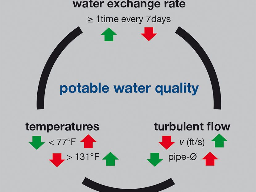
In Germany, the use of chlorine in drinking water is not regulated but minimized. The control of pathogens is accomplished through temperature control, water exchange and achieving turbulent flow.
This approach was discussed by Prof. Thomas Kistemann, head of the World Health Organization Collaborating Centre for Health Promoting Water Management and Risk Communication at Germany’s University of Bonn University, while speaking at the 2018 Emerging Water Technology Symposium in Ontario, May 15-16. He used the water quality triangle to illustrate the relationship of the water exchange rate, temperature and turbulent flow to achieve potable water quality.
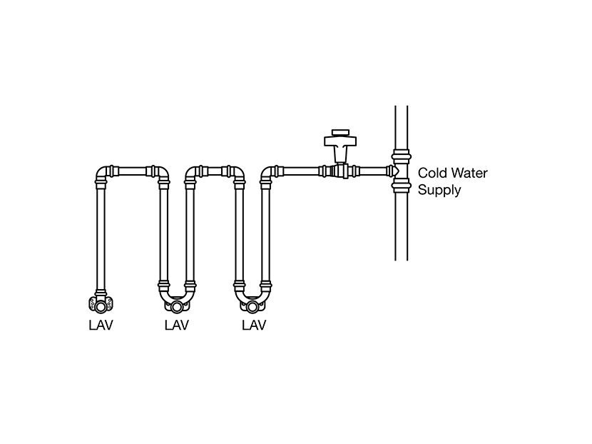
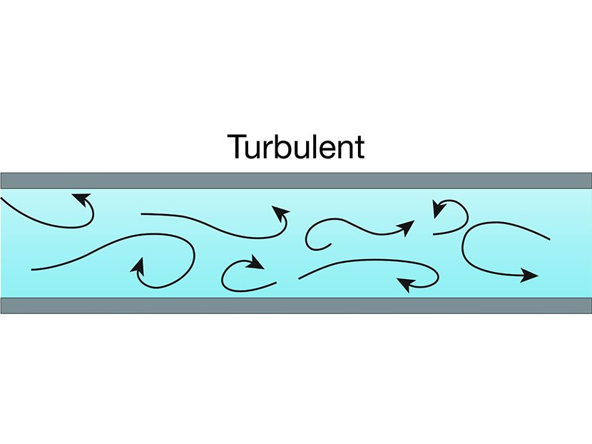
Series piping strategies are a popular approach to ensure water exchange. In addition to a series piping strategy to ensure good water exchange and biofilm control, turbulent flow is another goal for sizing the supply piping. Turbulent flow describes flow characteristics of water where there is a mixing effect of the water in the piping system.
A dimensionless number called the Reynolds number determines turbulent flow. A Reynolds number above 4,000 is considered turbulent flow. Other variables for determining turbulent flow include water temperature and pipe diameter.
Re=Dv/u
Re = Reynolds number
D= Diameter (feet)
v= Velocity (feet/s)
u = Viscosity
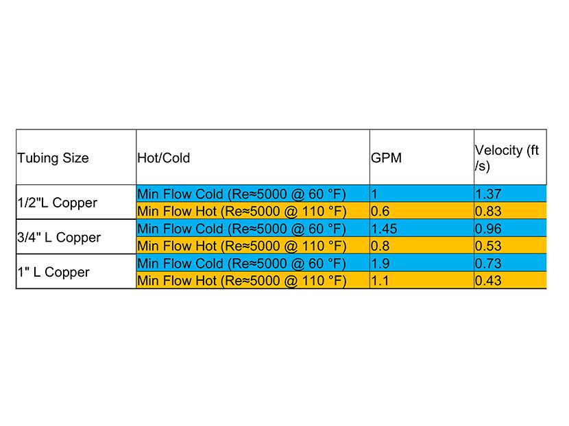
Table 1 illustrates examples of the Reynolds number for different water temperatures in different pipe sizes. Notice the turbulent flow is well below velocities that would cause erosion and corrosion issues.
ASHRAE Standard 188 and Guideline 12 recommend temperature control as a method to minimize the risk of Legionella outbreaks. Series piping allows for the plumbing engineer to minimize dead legs, which the standard requires. For this to be successful, it also requires fixtures to be grouped strategically.
In Germany, DIN 1988-300 is used for sizing domestic water pipe. Estimated peak flow varies by the type of building, such as a hospital, office building or apartment complex. This allows for smaller pipe sizing, resulting in better water exchange.
The U.S. uses more aggressive steps to size piping. The 2018 Uniform Plumbing Code introduced the peak plumbing demand calculator in Appendix M that can be used on residential and multifamily systems with water-conserving fixtures. It also would apply in multifamily housing units with central hot water systems.
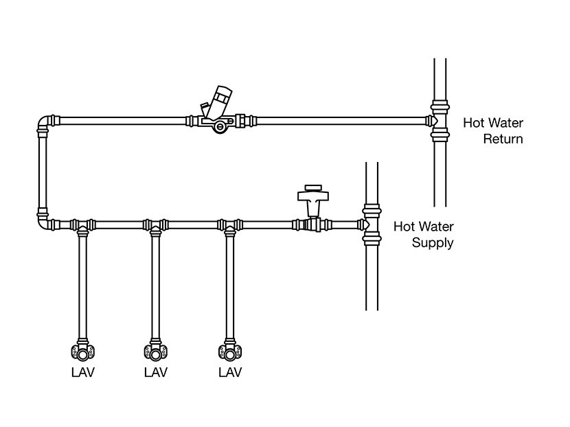
The length of the series piping is limited based on the hot water supply by the maximum distance allowed by this code and the customer expectations for hot water delivery. In situations where the maximum distance allowed by code is exceeded, the series piping system needs to be tied into the hot water recirculation system. However, this would create a challenge for balancing the recirculation system.
Hot water recirculation
Hot water recirculation is the process of circulating unused hot water back to the heating source to reheat and maintain a constant water supply temperature. In addition to its ability to mitigate the growth of bacteria, a hot water recirculation system’s other main purposes are the convenience it provides and the water it saves by minimizing the wait time for hot water to reach the fixture.
For any design other than infrequently used fixtures, such as those in industrial facilities or certain fixtures in office buildings, a delay of up to 10 seconds is normally considered acceptable. A delay of 11 to 30 seconds is marginal but possibly acceptable, and a wait of longer than 31 seconds is normally considered unacceptable and a significant waste of water and energy.
Water wastage caused by the long delay in obtaining hot water at fixtures has become as critical an issue as the energy losses caused by hot water temperature maintenance systems. To reduce the wasting of cooled hot water significantly, engineers have reevaluated the permissible distances for uncirculated, dead-end branches to periodically used plumbing fixtures.
Variables that impact the effectiveness of the hot water recirculation system include pipe insulation, pipe size, water temperature and ambient air temperature. The insulation impacts the heat loss of the piping system, which impacts the overall flow rate of the system. It also impacts how long it takes for the hotter water to cool down when the recirculation pump is not running.
The system in Table 2 compares how much heat is lost in the hot water recirculation system with double the insulation, the estimated time for the water temperature to cool down from 140 F to 124 F and the impact of pump sizing. The cool-down time was simulated and focused on the hot water riser and recirculation line.
The recirculation system used water at 140 F with a differential of 9 degrees for the pump sizing. Guideline 12-2000 recommends storage of water above 140 F and return temperatures above 124 F for Legionella control. Scald prevention would need to be considered and, in this example, the higher temperatures illustrate heat loss and time for piping to cool down.
The ambient temperature for the surrounding pipe is 68 F. By doubling the insulation, heat loss and flow is reduced by 26 percent. The time for the water to cool down also is increased, which would impact energy and water saving as well as keep temperatures outside of ideal growth range for Legionella.
Another strategy to reduce energy consumption and improve hot water delivery is by using a pipe-in-pipe system. The pipe-in-pipe approach works well in a situation where fixtures are grouped close together and are relatively close to the riser.
Balancing a recirculation system
The goal of a hot water recirculation system is for the temperature on each return to be the same. This is achieved through balancing, ensuring flow for each riser and branch. Without balancing, a recirculation system would be useless because the water would take longer to reach a hot temperature, thus wasting more water in the process. A properly balanced system with properly sized pipe and pumps not only provides fast water delivery and energy savings but will ultimately lead to lower material and operating costs.
Balancing is important not only for energy and water conservation but for mitigating Legionella outbreaks. Legionella growth is amplified in man-made water systems with stagnant water at warm water temperatures. Two of the biggest contributing factors to water-borne illnesses are stagnation and improper water temperature.
Keeping water temperatures outside of the growth range for Legionella makes it difficult for the bacteria to colonize. The bacteria cells become unable to reproduce at temperatures above 122 F. At temperatures above 131 F, the bacteria begin to die. Properly designing all parts of the system and maintaining a temperature above the highest colonization temperature reduces the possibility for bacteria to multiply.
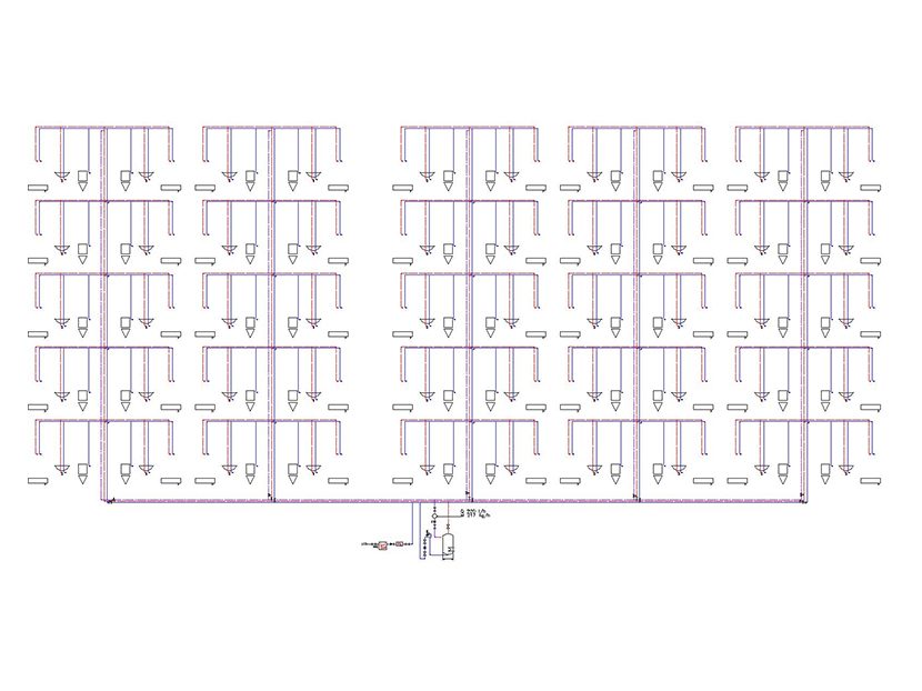
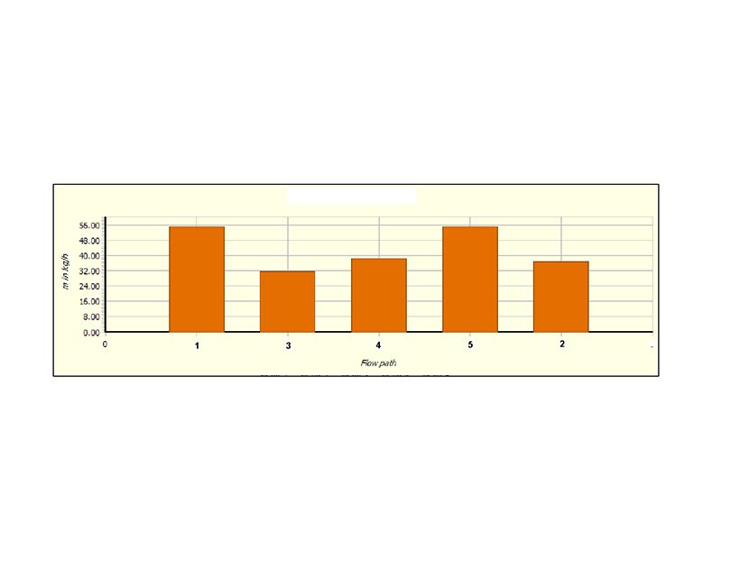
Hot water and hot water recirculation piping should be insulated to prevent excessive heat loss. All plumbing installations should minimize heat transfer between pipe at different temperatures. Figure 1 is an example of a building with five stories and five risers. The risers are not balanced on this example. Figure 2 shows the required flow needed to overcome the heat loss of the piping network. The flow varies because of differences in length from the source, pipe sizes and insulation thickness.
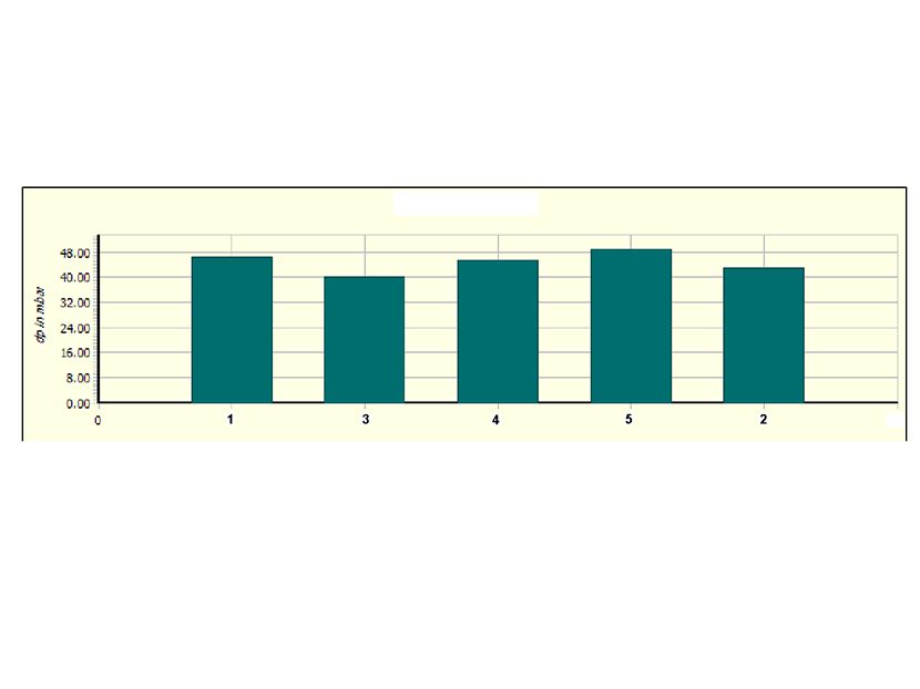
Each riser path has a different pressure drop when looking at it going to and from the heat source. The circulator size is based on the required flow for the system. The circulator needs to overcome the path or network with the highest pressure drop. In the sample project, the most demanding path is highlighted in Figure 3 and shows the total pressure loss of each path.
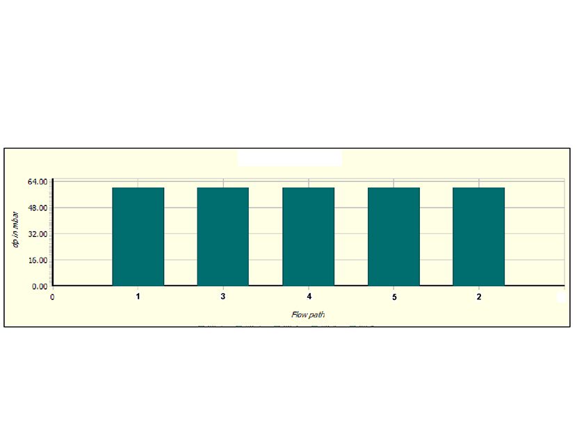
To ensure each riser has proper flow, the system will require balancing valves. Otherwise, water will take the path of least resistance, resulting in longer wait times for hot water, as well as wasted water or energy. When balancing valves are installed (Figure 4), the pressure drop in each loop equals out. The result is a balanced system.
Types of balancing valves
Also known as pressure-dependent balancing valves, manual balancing valves are one of the most popular types of balancing valves on the market, thanks to their affordability and availability. True to their name, these balancing valves are fixed for one condition and a change in pressure will result in a change in flow.
There are two types of manual balancing valves — variable orifice and fixed orifice — identified by the location of the pressure ports. A variable-orifice valve has pressure ports on both sides of the orifice and the valve opening is changed between pressure ports. It has a high differential pressure and is best used for low-flow applications. However, water impurities can lead to erratic pressure signals.
A fixed-orifice balancing valve has pressure ports located before the orifice, which does not change between pressure ports. It offers better pressure readings away from turbulence and, when compared to a variable-orifice valve, is faster to balance and less affected by water impurities.
A pressure reading is required, along with a chart or wheel, to verify the required flow in manual balancing valves. If any changes are made, all circuits need to be checked.
Unlike manual balancing valves, dynamic balancing valves are more common in hydronic applications and are pressure independent, meaning changes in the system pressure do not impact flow over a given range of pressure change. The flow is fixed in the branch and no calibration or field adjusting is necessary. With dynamic valves, valves and cartridges are specifically set for a differential pressure range and flow. As the pressure differential increases, a spring compresses and the flow path begins to close, but flow remains fixed at a cross valve.
Thermal balancing valves are some of the newest types of valves on the market for new and retrofit applications. Unlike automatic and manual valves, thermal valves never fully close or change flow based on a temperature set by the user or preset on the valve. Some manufacturers offer thermal valves in a number of configurations and are compatible with various accessories for better functionality. Besides the flexibility of only needing to set the temperature once, other benefits of thermal balancing valves include remote monitoring, easy troubleshooting, thermal disinfection and the option of adding a built-in isolation valve.
To balance the system, the goal is to have the same water temperature on the return of the recirculation system. Different balancing valve technologies are available to help achieve this goal. As fixtures are used or if ambient temperature changes, the design conditions of the system are now different.
The thermostatic balancing valve dynamically changes with the system. As the return line cools down (i.e., low fixture use), the valve opens. In case the return temperature heats up (i.e., high fixture use, ambient condition change, summer temperatures, etc.), then the valve will start to close but will never completely shut. Ultimately, the valve changes to the demands of the system.
The valve has a wide range of temperature settings and can incorporate visual indicators of temperature (thermometer), which is great for visual inspections. On larger projects, a temperature sensor can be installed instead of the thermometer, then tied into the building management system and monitored centrally. For areas with smaller flow rates (i.e., branches), adjustment of the cross valve could be helpful in situations when a requirement exists for fixtures to tie back into the recirculation system.
The ability to maintain flow in a hot water system offers several benefits. Moving water makes it harder for bacteria to establish itself along a pipe wall. Bacteria immersed in flow does not have the opportunity to settle on the pipe surface. Water exchange can help maintain temperature. Stagnant water allowed to cool is displaced with higher-temperature fresh water from the heating source, which makes it easier to maintain temperature. This also reduces the wait for hot water at the fixture, which promotes user comfort and convenience.
However, a recirculation system cannot provide these benefits unless it is properly balanced. Therefore, it is important to incorporate some type of balancing valve into the design considerations so the temperature on each return is the same. A properly balanced recirculation system offers health and safety benefits. And by wasting less water and reducing the wait time for hot water to reach a fixture, you’ll reap major energy and efficiency benefits, too.


