DHW Return Design: Doing It Right and the Risks of Doing It Wrong
As the difficulty in designing and balancing these systems increases with system size and complexity, so does the importance of doing it correctly.
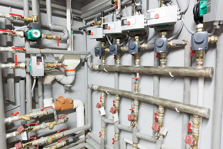
One of the most common plumbing system issues I’m brought into near punch list time or shortly after occupancy is inadequate water temperature at a fixture or in a general area. Those experiencing the issue often have their own ideas about what’s causing it: the water heater temperature is set too low, the circulating pumps are sized too small or the mixing valves were not chosen correctly.
However, in my experience, 95% of the time the issue is that the domestic hot water (DHW) system was not properly balanced or sometimes not balanced at all. If this is the case, attempting to correct the problem with other measures is far less likely to succeed and may further compromise the design intent.
While user satisfaction is often the first thing that triggers awareness of a balancing issue, it is not the only reason why proper balancing is important. When water to a fixture does not get hot fast enough, users will run the water longer while waiting for it to heat up, resulting in both wasted water and the energy it takes to heat it. Perhaps worse, especially in health-care applications, inadequate hot water can result in inadequate hand washing and sanitation.
Improper balancing can also result in hot water loop temperatures dropping to where they favor Legionella and other waterborne pathogen growth. Given all these risks, the importance of proper hot water return design and balancing should be apparent. Fortunately, there is a formulaic way to design a properly balanced system as well as specification language making enforcement easier.
Hot Water Return and Balancing Design Process
When DHW is circulated through multiple loops, it will take the path of least resistance (i.e., the path with the least pressure loss). As such, an unbalanced system will see plenty of hot water circulation through the shortest loop with the largest pipe, but little to no flow through the others.
A properly balanced system ensures that losses in each loop are equalized; therefore, the water does not have a preferred path. Balancing valves are placed in each loop to equalize these losses while delivering a circulation flow rate that keeps the water in a specified temperature range.
Designing a properly balanced DHW system often occurs toward the end of the construction document phase of the project. To determine how the system should be balanced, the hot water supply piping must be routed and connected to all fixtures on the drawings and properly sized. Once this is done, you can route the DHW return piping back to the source equipment.
You can also take educated guesses at what the proper size of the return piping should be, which you’ll confirm later with calculations. Once this is done, designing the hot water return piping generally follows these steps:
Identify the domestic hot water loops.
Determine your acceptable temperature drop through the loop (or back to the source equipment).
Determine the type of balancing valves you will use (which you choose can greatly simplify some of the next steps).
Place balancing valves on the hot water return piping.
Calculate the flow rates needed to achieve your temperature drop.
Calculate the pressure losses through each hot water loop at the calculated flows.
Confirm the sizes of your hot water return piping.
Choose a circulating pump that can achieve the total return flow at the highest calculated loop loss.
Identifying the DHW loops is the easiest step in the process. Engineers often determine their strategy for separating a building into DHW loops early in design development or sooner. Strategies can depend on the type of building, number of floors, floorplan layout, functional areas, ease of construction, and more.
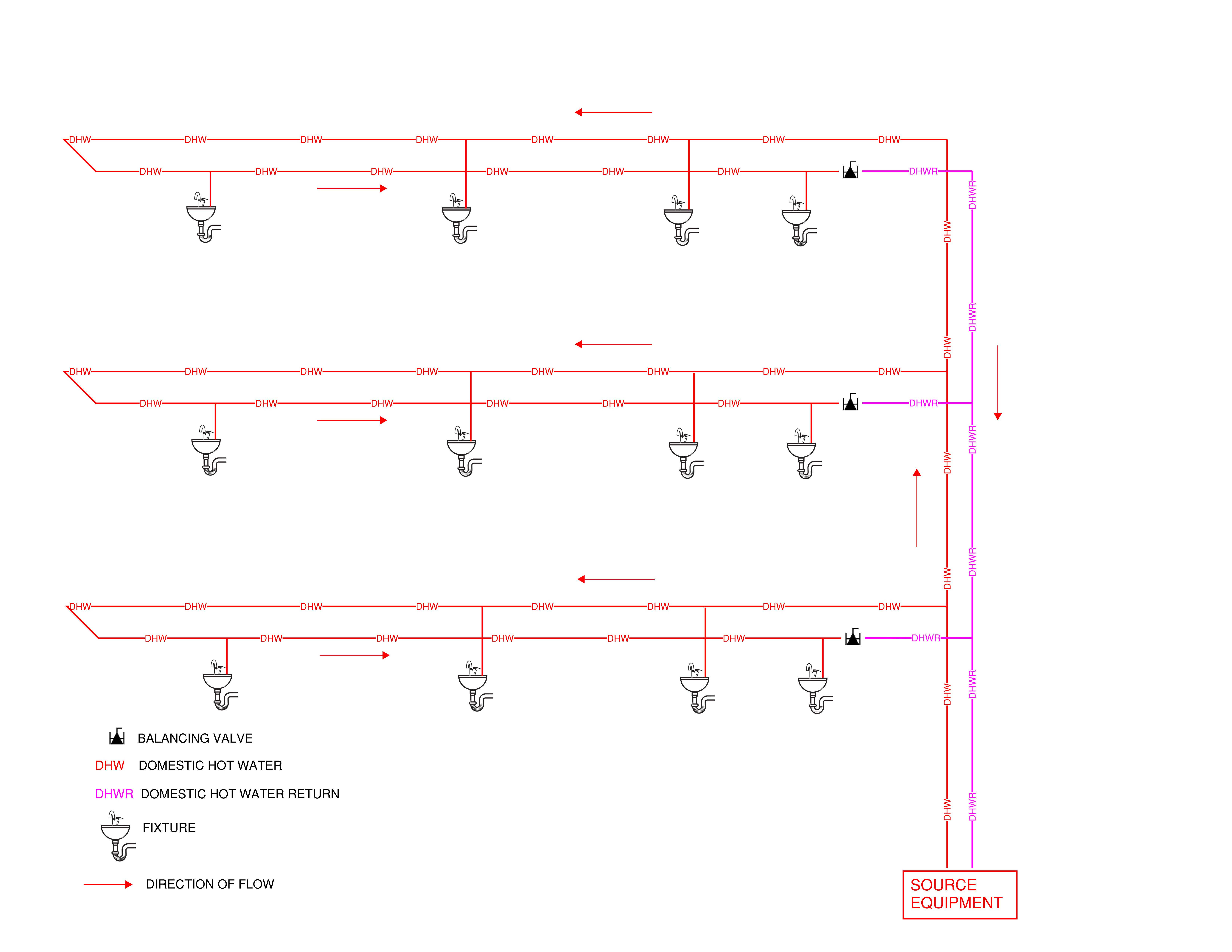
For example, many health-care buildings often include domestic hot water loops for each floor (Figure 1), and these may be broken up into smaller loops for dedication to different patient and staff functional areas.
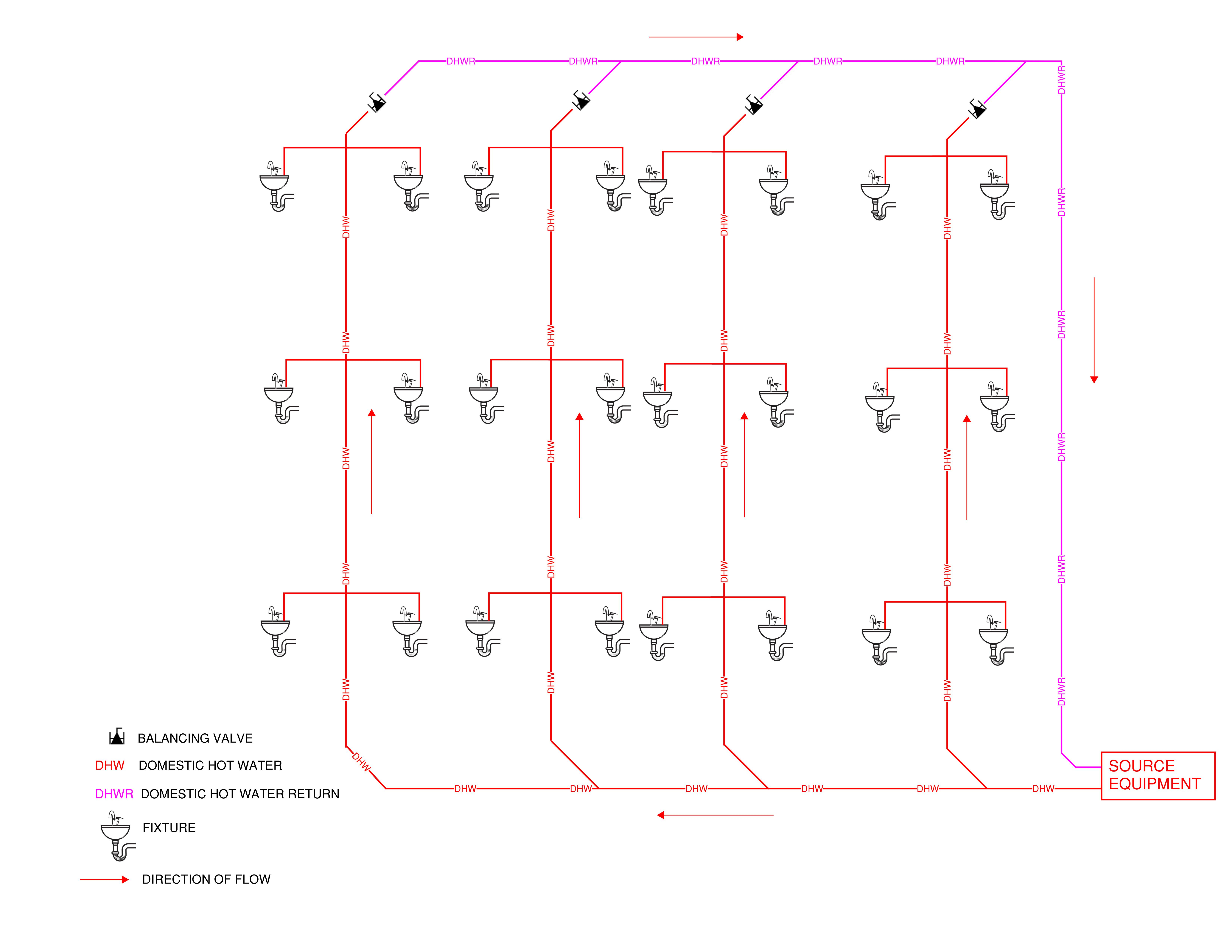
Hotels, apartments and, occasionally, hospital bed towers where floor plans are stacked or substantially similar often include multiple water riser sets feeding adjacent rooms on each floor (Figure 2). Whatever your strategy, identify the number of loops you must determine the number of balancing valves you need to design for.
To determine your acceptable temperature drop through each loop (or back to your source equipment), you need to consider several factors. The first factor is what the minimum temperature at the most critical fixture is.
For example, many health codes require a temperature range of 105 F to 120 F at the fixture outlet in clinical areas. Therefore, if the DHW distribution temperature is chosen to be 115 F, the loop must be designed for a temperature loss of no greater than 10 F.
In addition, some fixtures and equipment in the loop may have their own temperature requirements that must be designed for, such as individual mixing valves needing a supply temperature at a given level above their setpoint to operate.
Another factor to consider when choosing your loop temperature loss is the risk of Legionella and other waterborne pathogen growth. Legionella bacteria grow in temperatures between 68 F and 122 F and rapidly between 77 F and 108 F. Therefore, it’s prudent to keep your entire loop temperature out of this danger zone and choose a temperature loss that maintains it.
For example, setting the supply temperature at 125 F while designing for a 10-degree loss will still drop much of the loop into temperatures where Legionella can grow. Keep in mind that staying out of these temperatures may be less of a concern if your water system is equipped with chemical, ion or other supplementary bacterial control measures.
Selecting the Right Balancing Valve
Choosing the type of balancing valves you will use has a great influence on the rest of the process, as well as the ease of balancing the system during construction. The three types commonly seen are manually adjustable variable flow, fixed flow and thermostatic.
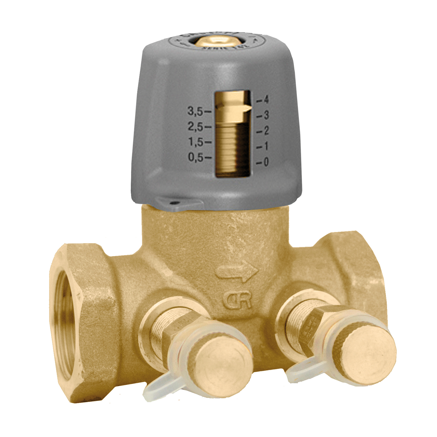
Manually adjustable variable-flow types (Figure 3) were the most common type until recent years when technology improvements gave rise to the other two. A contractor adjusts these manual valves near the end of construction to achieve the flows calculated by the engineer.
However, adjusting one valve will often change the losses and flows seen by the others. This iterative process becomes increasingly difficult and time-consuming as the number of hot water loops increases and the valves may still need to be occasionally adjusted afterward.
Automatic fixed-flow valves (Figure 4) are becoming more common now due to their advantages over manual valves. These valves automatically adjust loop losses with changes in hot water demand but never deviate from the flow they are set to. Therefore, the contractor will install valves meeting the flow settings calculated by the engineer without any need to balance the system.
This can mean a large savings in time and labor for the contractor, along with greater assurance for the engineer that the DHW system will operate as designed. The engineer still must calculate balancing valve flows meeting the required temperature drop to select the valves and verify that these flows keep the water moving at an ideal velocity (2 to 3 feet per second).
Thermostatic-balancing valves (Figure 5) are the newest innovation in this area. These valves adjust the flow with changes in hot water demand to deliver a constant water temperature at their outlet. Like fixed-flow valves, they do not require the contractor to balance the system and carry the same advantages that come with it. The engineer should still determine the flow the temperature setting corresponds to so the water velocity again falls within 2 to 3 feet per second.
Additionally, thermostatic-balancing valves operate within specific hydraulic ranges and will not work if the temperature they are set to corresponds to a pressure outside this range. As such, you need to select valves with a hydraulic range suited to your calculated flow rate.
Balancing-Valve Placement in DHW System
After choosing your balancing-valve type, it is time to place them in your DHW system. The constant rule of placing these valves is that they cannot be arranged in series — this causes one to adjust to changes in the other in a constant cycle. Beyond this, best practices for placement have changed with the evolution of plumbing engineering.
In the past, many engineers placed a single valve immediately after the last fixture in the loop since they only cared about user satisfaction and maintaining the temperature up to that location. With the increase in research and concern around waterborne pathogens, we now know that this strategy is not always the best because any length of pipe downstream of the balancing valve was left unaccounted for in temperature maintenance calculations, left to cool to levels favorable for pathogen growth.
It is often better to place the balancing valve at the very end of the loop before it connects to a common hot water return main. This way, the entire loop is accounted for. However, it is still important to account for the common return main each loop connects to; otherwise, it will also cool to unfavorable temperatures. Accounting for the main involves including it in one or several of your balancing-valve flow calculations.
Flow Rate, Heat and Pressure Loss Calculations
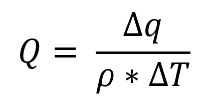
Once the balancing valves are placed, you should next calculate the flow rate for each valve meeting your temperature loss requirement. The equation for calculating this is:
where
Q = flow (gallons/hour)
Δq = heat loss through the hot water loop (BTU/hour)
p = density of the fluid in the loop (pounds/gallon)
ΔT = temperature loss through the loop (°F)
Assuming the fluid in the pipe is water with a density of 8.31 pounds/gallon, a temperature loss of 5 degrees and converting units to give us a flow in gallons/minute, the equation simplifies to:
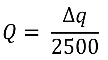
Determining the heat loss in the loop requires adding up the heat loss for each given segment of a given pipe size. Heat loss calculations for this situation, especially with insulated pipe, are complex, so most engineers rely on published empirical data for common scenarios. Figure 6 illustrates values often used for copper pipe insulated with given thicknesses of fiberglass insulation meeting conductivity ranges of ASHRAE 90.1-2013.
With these equations and heat loss values, you can build a heat loss table (Figure 7) for each hot water loop in your building and calculate the required flow for each balancing valve.
After calculating all your balancing valve flows, you can then calculate the pressure losses due to friction through each loop (Figure 8). The loss charts for various pipe sizes at given flows are readily available in most plumbing codes. Be sure to include additional loss for fittings and changes in direction, often as low as an additional 30% for loops with few fittings and as much as 50% for loops with many.
As with the balancing-valve flows, you will also need to account for the length of pipe in a common return main.
After you have calculated all balancing valve flows and loop losses, go back through all your DHW return piping and ensure that it is properly sized. Ideally, water velocities in the hot water return piping should be in the 2 to 3 feet per second range — less increases the risk of stagnation and pathogen growth, and more may erode the pipe faster, especially copper.
You may also want to revise pipe sizes if the friction losses become unreasonable, but not at the expense of the ideal velocity range. If you revise any return piping sizes, be sure to recalculate the corresponding balancing-valve flows and loop losses.
With all your calculations complete, you can then choose a circulating pump. The pump needs to meet the total flow of all the balancing valves at the highest loop friction loss you calculated. Depending on your building type, system demands and risk tolerance of the owner, you may want to arrange two pumps in parallel for redundancy with lead/lag controls.
Specifications and Construction Tests
Following the previous steps is often not enough to ensure that your DHW system will be installed properly. Your specifications should be very clear about the type of balancing valves you designed for and approved through the normal submittal process.
While some contractors still prefer manually adjustable balancing valves because they’ve used them for years, more are eager to use one of the other types to eliminate balancing completely. Even so, if there is a chance of manually adjustable valves being installed, you should require the contractor to submit a balancing report (Figure 9) near project closeout.
The balancing report should include sizes, locations, makes and models of each balancing valve in the system, along with the flow achieved for each. Flows within 10% of those you calculated are usually acceptable. Specification language should include your right to have them balance the system again if any fall outside this.
Balancing a DHW system is often as much an art as it is a science, and many plumbing contractors hire a specialized balancing subcontractor to do it. Oftentimes, the subcontractor balancing the DHW system is the same as the one performing test and balance for the HVAC systems. If commissioning is required for the building’s HVAC systems, it is best to include DHW balancing as part of the exercise.
Modern design of a DHW return system is about much more than keeping users satisfied with hot water arriving quickly at an acceptable temperature. It is about keeping waterborne pathogens at bay and keeping energy and water usage down. As the difficulty in designing and balancing these systems increases with system size and complexity, so does the importance of doing it correctly.
Aaron Bock, PE, has been designing plumbing systems for the health-care industry nationwide for more than 16 years. He is a past president and current vice president-legislative for the Wisconsin chapter of the American Society of Plumbing Engineers.


