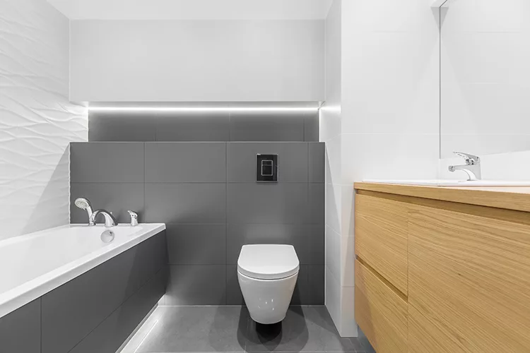
A new water closet type from Europe recently entered the United States market. Known as an in-wall tank water closet (ITWC), the plumbing fixture is wall-mounted with a concealed tank inside the wall. It comes with a carrier designed to bolt to the studs in the wall to contain the tank and provide proper support for the bowl. Since it is a tank-type water closet, a 1/2-inch cold water connection is required to fill the tank.
The bowl includes a 90mm plain-end back outlet; manufacturers provide specialty waste fittings for transitioning from the bowl outlet. The waste fittings come with a 90mm specially configured inlet with an O-ring gasket designed for a “push on” connection to the bowl outlet and transitions to a cast-iron 3-inch hubless outlet.
The waste fittings are also configured as straight or quarter bends; only one manufacturer makes additional configurations. Plastic fittings are made of polypropylene (PP) or high-density polyethylene (HDPE). These materials do not meet ASTM E84 for the 25/50 smoke flame rating. However, this is not an issue since the fittings are installed inside the wall and not inside a return air plenum.
PP and HDPE fittings are not listed in the plumbing codes for aboveground or belowground building drainage piping. Because manufacturers provide these fittings for use with their products, most authorities having jurisdiction (AHJs) will allow them to be installed. They are only used at the water closet outlet to transition to horizontal flow or down through the floor.
These plastic fittings may not be allowed in jurisdictions such as Boston, New York City, Los Angeles or Chicago. This article focuses on iron fittings for use in these jurisdictions.
Cast iron as straight or quarter-bend waste fittings are available from manufacturers. The 3-inch, cast-iron quarter-bend waste fitting drops from the bowl outlet to below the floor. This fitting requires a 6-inch stud wall, while the PP or HDPE quarter-bend waste fitting can fit inside a 3 5/8-inch stud wall.
ITWC Venting Configurations
So, how is the ITWC vented? Henderson Engineers has discussed this subject extensively with various manufacturers; the conclusion is that venting the water closet is the responsibility of designers and engineers. Therefore, we performed a process improvement to determine how best to vent ITWCs.
If an ITWC is installed in a 3 5/8-inch or 6-inch stud wall, the flush tank and carrier block the vent installation in the wall from the quarter-bend 3-inch waste fitting located below. Also, note that there is no vent connection with the waste fittings. So, the vent must be located outside of the carrier. Figure 1 is an example using cast-iron, quarter-bend 3-inch waste fittings for venting the water closet with a 3-inch by 2-inch wye combo on its back.

What if ITWCs are installed back to back? A solution is to vent each water closet as previously described with the 3-inch by 2-inch wye combo fitting on its back (Figure 2). Locate the 3-inch waste under the centerline of each quarter-bend 3-inch waste fitting. Combine the 3-inch horizontal wastes with a 3-inch upright wye fitting on its back and rotate slightly from vertical.

What if ITWCs are installed in a bathroom group or unisex toilet room with a lavatory? Can an ITWC be wet-vented? If the ITWC is in a bathroom group, the answer would be “yes.” If the ITWC is in a unisex toilet, the answer is “maybe” and should be approved by an AHJ. Figure 3 is an illustration of a wet vent installation.

What if ITWCs are installed back to back and stacked vertically? They must meet Americans with Disabilities Act (ADA) requirements and be centerline 18 inches off the wall, restricting vent, soil and vent stack locations.
Figure 4 shows a vented closet cross with a 2-inch top vent between the ITWCs. HDPE straight 90mm waste fittings are used at the water closet outlets. They are connected to the closet cross with a shielded transition coupling.
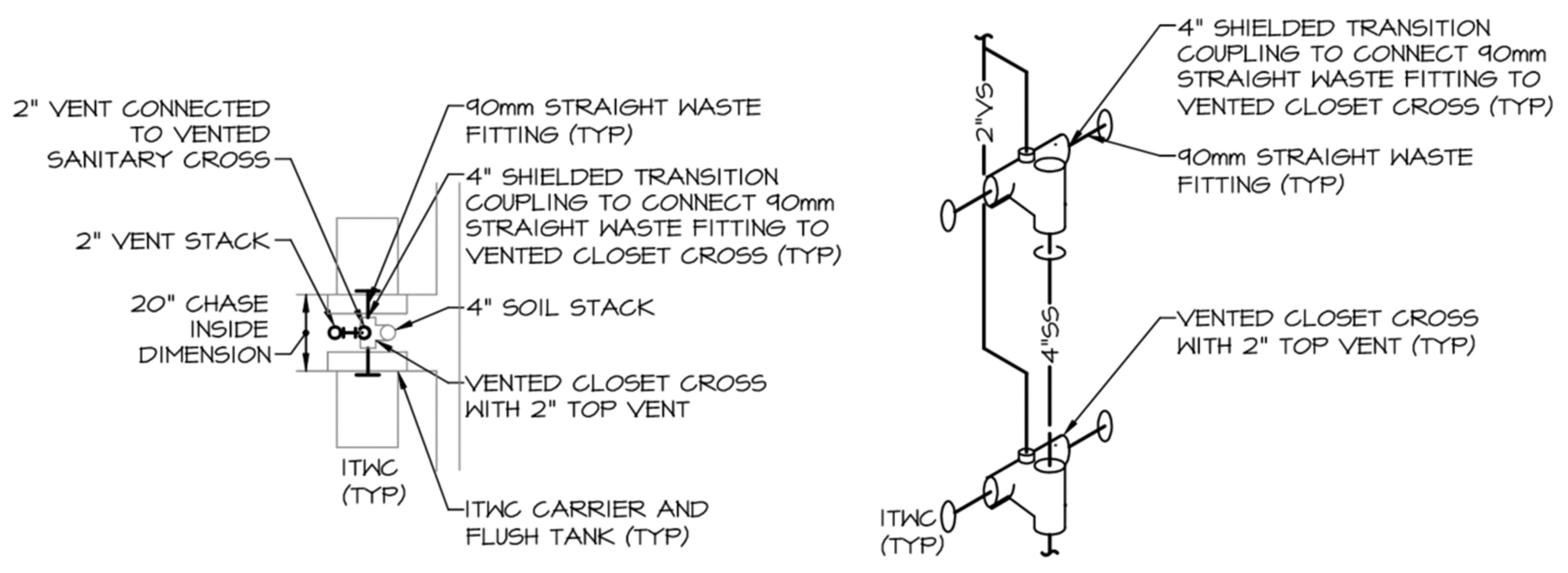
The chase width is 20 inches inside clear, and 6 inches is used to install the straight waste fitting and shielded transition coupling (6 inches is chosen because no dimensioned drawings are available of the straight waste fitting; it is not clear dimensionally where the water closet outlet is from inside the wall).
The advantage of this fitting is that there is no separate soil stack or space for a separate soil stack. In this case, the ITWCs must meet ADA requirements and be installed 18 inches off the wall. Note the ample space for the vent stack, soil stack and water riser (not shown for clarity) between the carriers.
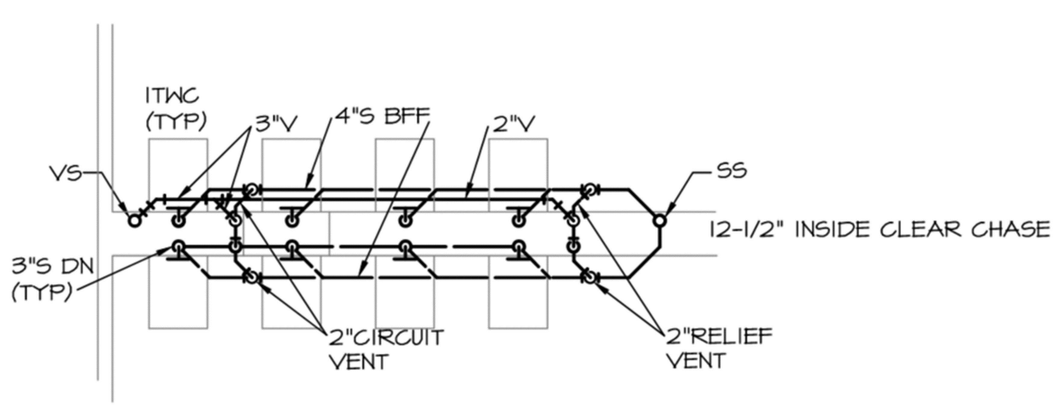
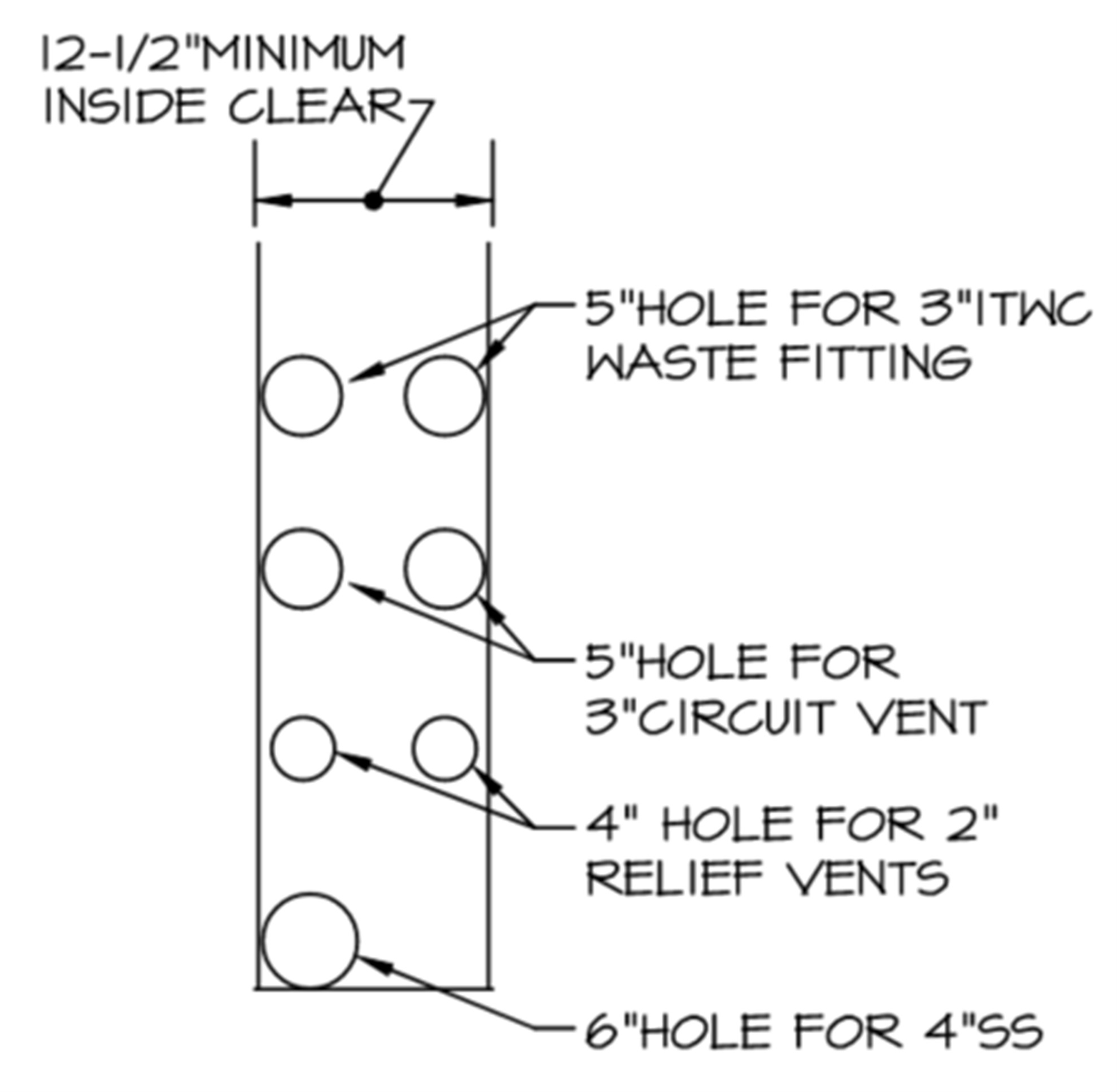
What if multiple ITWCs are installed back to back for battery installation in public toilet rooms? In this case, a circuit vent is used (Figure 5). The water closet must enter the circuit vent in the horizontal. This makes it impossible for the circuit vent to run underneath the quarter-bend 3-inch waste fittings, for they would enter the circuit vent vertically, which is against the codes. A chase width of 12 1/2 inches inside clear was provided based on spacing across the chase for the sleeves or cores through the slab (Figure 6).
One ITWC manufacturer offers a cast-iron, quarter-bend waste fitting with a heel inlet. A cleanout plug is factory-provided with the fitting. A hubless X, screwed cast-iron adapter can be installed to connect a 2-inch vent. The vent connection will be under the flush tank. To route the vent out of the wet wall or connect to a vent header, additional space must be provided behind the carrier and flush tank.
Henderson Engineers recommends a minimum of 4 inches to install the vent and pipe supports. This would require a 5-inch by 10-inch rectangular hole in the slab for the 3-inch waste fittings. This pipe penetration may not be properly fire-sealed to achieve some rated floor penetrations. A solution is to provide separate 5-inch holes 2 1/2 inches apart for each waste fitting, setting the chase width to 16 inches (Figure 7).

ITWCs are new to the United States market; their in-wall tank design offers a footprint smaller than conventional tank or flush valve types. They offer an aesthetically pleasing look that many agree is their prominent feature. Furthermore, they are tank-type water closets, so an upsized water distribution system is unnecessary.
However, their waste system differs from other water closets in the United States today. Innovation is required to properly vent and pipe the waste with proven vent techniques and fittings. There may be different ways to accomplish this; further research is needed. Pipe and fitting manufacturers in the future may also offer more waste fittings, giving designers and engineers more venting options.
Warren Rosenbrook, PE, CPD, FASPE, is the plumbing technical director at Henderson Engineers, a national building systems design firm.
