Designing Hydronic Snow and Ice Melting Systems
Expert tips to optimize performance and efficiency.

Following another crazy long winter across North America, spring is the season to help your customers prepare for next winter by teaching them about the advantages and savings of hydronic snow and ice melting (SIM) systems.
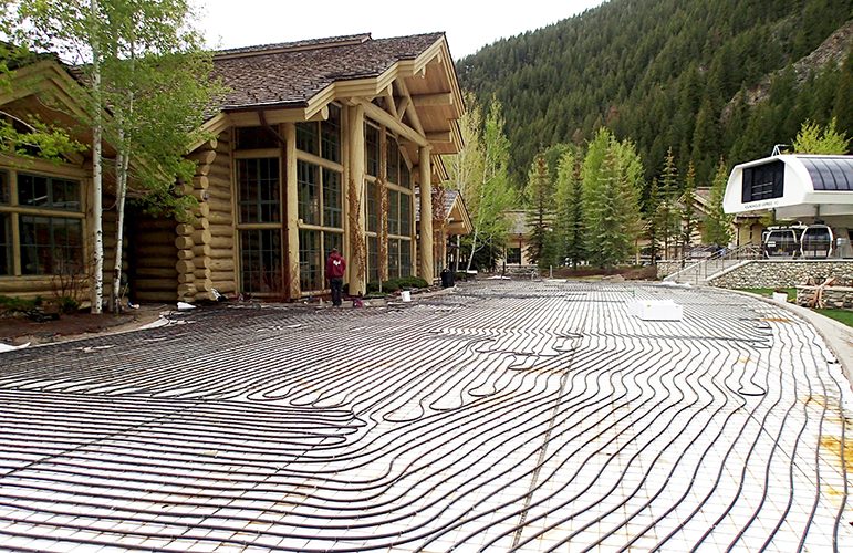
These systems augment the removal of snow and ice by circulating a heated fluid such as glycol and water through tubing installed within almost any outdoor area. Pioneered in the 1940s using wrought iron or steel pipe embedded in concrete, these systems moved to copper tubing in the 1950s and 1960s.
Modern SIM systems use flexible PEX or PE-RT tubing, the same products used for radiant heating systems. In fact, some people think of SIM systems as outdoor radiant heating systems, but they are much more than that.
SIM systems are used in a wide variety of applications all over North America. Examples include sidewalks, steps, driveways, ramps, parking lots, loading docks, carwashes, roadways, bridges and helicopter landing pads. They are also used at hospitals, train stations, airports, hotels and ski lodges.
Most of these types of areas can be considered as high-traffic/high-hazard situations where 24/7 accessibility might be required. Still, many SIM systems are also found in private residences for driveways, walkways and steps.
Who Can Afford a SIM System?
The myth is that these systems are a luxury for the top 1%, but the annual operating costs for a SIM system can be significantly less than for mechanical snow removal and, in fact, provides a safety and convenience benefit.
It takes considerable energy, delivered in short bursts, to melt snow and evaporate the water. However, these systems are usually standing by, consuming no energy unless it’s snowing or they are set in idle mode. In many locations, the actual operating time of a SIM system is less than 200 hours per year.
For many residential systems, the operating costs can be less than $500/year, thanks to efficient heat sources. This cost is probably much lower if the outdoor area is only a 1,000-square-foot driveway. This means that a hydronic SIM system can offer 50% to 80% savings versus annual costs for hiring a snow removal contractor. And if it doesn’t snow, operating costs are zero.
For certain commercial applications, the annual cost of operating the SIM system is almost negligible compared to the energy costs for heating a large building. In buildings with year-round cooling demand, such as data centers or hospitals, the piping network in the snow melt area can be used to help reject heat from the building to the atmosphere, requiring only the power of a circulating pump. In other words, a parking lot or walkway can be part of the heat rejection system, even when it’s not snowing.
The reality is that many families and businesses can afford to operate a hydronic SIM system if it’s designed, installed and controlled correctly.
SIM Design Tips
Melting snow and ice is basically a three-step process:
1. Heat the snow or ice to its melting temperature; the heat capacity of snow or ice is 0.51 Btu/lb.
2. Add more heat to melt the snow into cold water; the latent heat of fusion to change its phase is 144 Btu/lb.
3. Evaporate the water, changing its phase again. In many installations, the majority of the water simply drains off, saving energy. Otherwise, making the steam rise off the driveway takes quite a bit of energy, especially on a humid day.
Much of the information available to SIM designers comes from the American Society of Heating, Refrigeration and Air-Conditioning Engineers (ASHRAE) HVAC Applications Handbook. Chapter 52 guides designers to use SIM heat loads from a table for U.S. cities or manually calculate loads using equations and available weather data from sources such as Environment Canada or the National Weather Service.
Environmental factors affecting SIM heat loads include the air temperature when snowing, snowfall rate, snow density, wind, humidity level of the atmosphere and even the “apparent sky temperature.” With so many variables, the most difficult design issue is estimating loads. For this reason, it’s best to manage expectations by using the term “estimate,” not “predict.”
As you can imagine, there’s a wide range of performance requirements for different applications. Heating loads for these outdoor systems can be in the range of 50 to 400 Btu/ft2 per hour, depending upon the project location and customer requirements. Determining the appropriate heat load has a significant impact on initial installation costs, affecting the size of heat sources, gas piping, boiler piping, circulators, etc.
Selecting Performance Levels to Meet Customer Requirements
Unlike in an indoor heating system, where the methods to calculate minimum heating loads are well-defined, for SIM systems, the designer and customer collaborate to select the capability of each system based on the type of outdoor area and customer expectations.
ASHRAE handbook Chapter 52, Snow Melting and Freeze Protection, Table 1 includes heat fluxes for 46 major U.S. cities listed in six columns labeled as percentages (see Figure 1). These are frequency distribution columns that indicate heat loads in Btu/ft2 per hour required to meet those percentages of operational time. For example, a 95% value indicates that 95% of the time, the snow-melting load should be at this value or lower.

These values are based on 30-year-old weather data, but it’s still the best guidance available, with the exception of local experts for a particular location.
In Figure 1, each city also has three rows referring to Snow-Free Area Ratios defined as follows:
Ar = 1.0 snow-free area of 100% or no accumulation during snowfall
Ar = 0.5 snow-free area of 50% or some accumulation during snowfall
Ar = 0" snow-free area of 0%, meaning the surface may be covered with snow during heavy snowfall, melting snow from the bottom of the layer
Although having the SIM area free of snow during the snowfall is preferred, maintaining an Ar of 100% requires the system to melt snow on contact — far more energy than if a small layer of snow is allowed to accumulate on the surface during the snow event.
An Ar of 0% means you might see a layer of snow during the snowfall, but once the snowfall slows down, it will melt and then evaporate to leave a dry surface; it’s only a question of time. It’s also a question of required safety and access.
For instance, a hospital entrance in Duluth, Minn., expected to keep up with 100% of expected snowfalls may be sized to output 370 Btu/ft2 per hour at worst-case conditions. This doesn’t mean the system will always require 370 Btu/ft2 per hour, but the designer might want to specify the system to meet that capacity for the worst expected blizzard for such a critical facility.
On the other hand, a residential driveway in Washington, D.C., might be sized for lower output, even as low as 75 Btu/ft2 per hour. This system might not keep up in a historical blizzard, but it will catch up and leave a dry surface a few hours later. Designing for a lower capacity can significantly reduce the mechanical system costs (e.g., boiler, circulator).
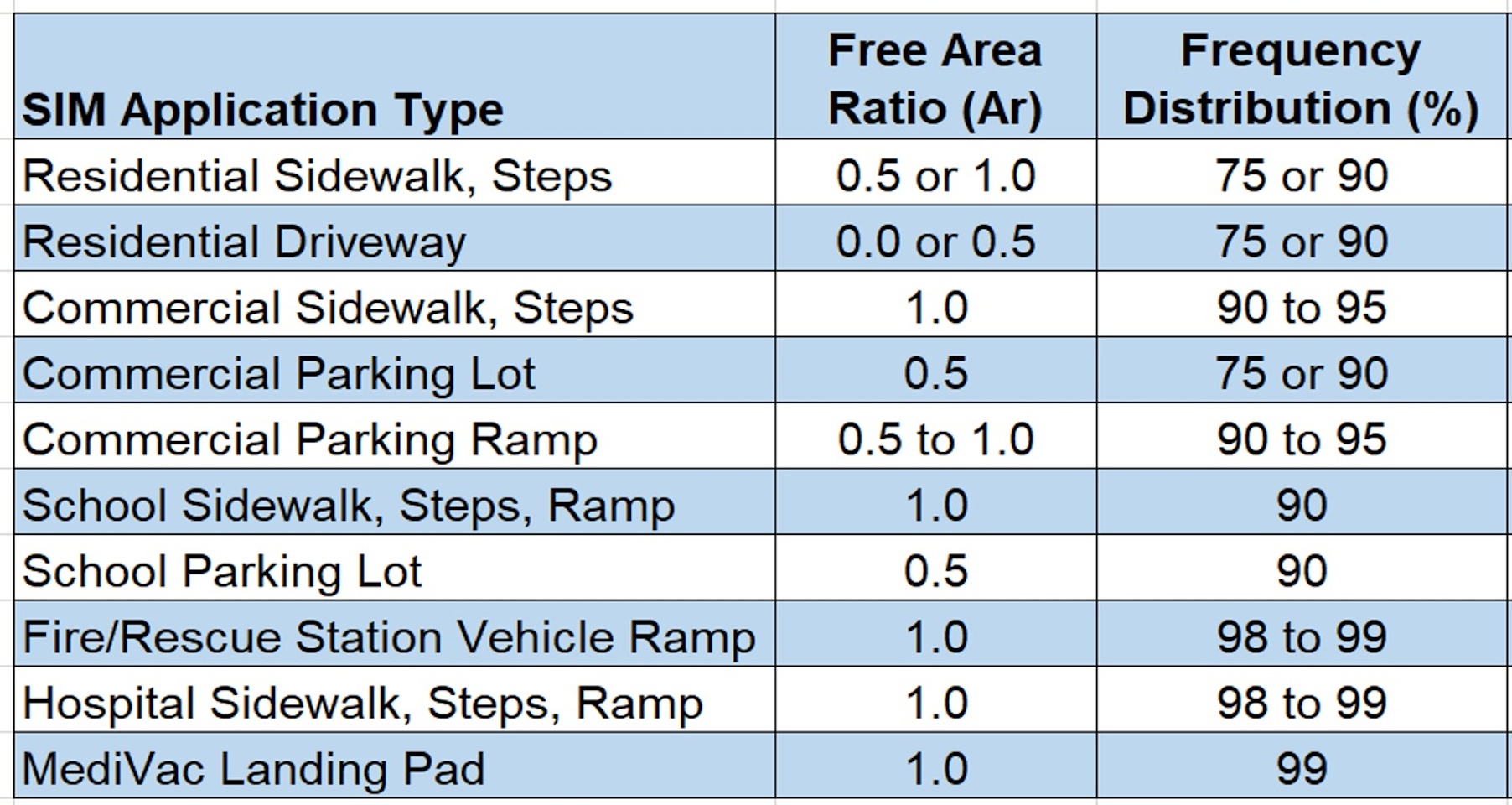
Figure 2 includes suggested snow-free area ratio and frequency distribution values for common SIM applications to help manage customer expectations and construction costs. For example, does a residential driveway need to be designed to be 100% snow-free during 100% of historic snowfalls? Probably not. However, a medivac landing pad should be 100% snow-free during the worst weather that the unit can operate.

Once the design requirements are selected, then heat flux loads can be taken from ASHRAE’s Table 1 or calculated manually from weather data. Be sure to account for downward losses because the frozen earth will absorb significant thermal energy from a heated area. Codes dictate insulation requirements, usually minimum R-5, but 1 1/2 to 2 inches of extruded polystyrene foamboard is typical.
However, since the earth is such a massive heat sink, there could be 20% downward losses even with this level of insulation.
Once the estimated loads are known, hydronic calculations such as flow rates and head loss are next. Make sure sufficient antifreeze is selected at a high enough concentration to keep the fluid in a liquid state at cold temperatures when calculating flow rates and head loss.
For the equation shown in Figure 3, values for fluid density (FD) and specific heat (SH) must come from the manufacturer of the antifreeze. Sixty converts hours to minutes, and the delta-T recommended for most SIM systems is 25 F. With a 50/50 mixture of water and propylene glycol, such as Dowfrost, with an FD = 8.86 and an SH = 0.83, the bottom value of the equation becomes 11,030.

For head loss through the piping, the Plastics Pipe Institute (PPI) has a free online tool at www. plasticpipecalculator.com.
Tubing Design and Installation
Installation of the tubing used for SIM systems is similar to radiant heating but with different thermal mass possibilities, such as concrete, pavers or asphalt. Each type of surface has its own techniques for optimal installation. PPI and most tubing manufacturers provide guidance with these details.
SIM systems usually require high flow rates, so 3/4-inch nominal PEX or PE-RT tubing is typical in commercial projects. Larger-diameter tubing is occasionally used for very large projects. Residential projects often use 5/8-inch nominal tubing, and 1/2-inch tubing is normal for placement on stairs when tight spacing and low profile are required.
Mechanical codes provide tables with maximum circuit lengths for SIM systems, but actual circuit lengths are based on flow rates, pressure drop and the selected circulator.
To provide rapid and even melting, 8-inch to 9-inch tube spacing is typical, even tighter in critical areas. However, going wider than 9 inches runs the risk of snow strips between tubes, an unsafe situation. See Figure 4 for typical piping design values.

By applying hydronic technology to outdoor surfaces, snow and ice melting systems deliver efficient and reliable performance, keeping outdoor residential and commercial surfaces clear and safe, and reducing operating costs while helping the environment. Reducing the use of ice-melting chemicals and protecting outdoor surfaces from snowplow damage is a beneficial, sustainable application of hydronics.
Lance MacNevin, PEng, is the director of engineering for the Plastics Pipe Institute’s Building & Construction Division and has been in the plastic pipe industry since 1993 in various technical roles. He serves on technical committees within ASHRAE, ASPE, ASTM International, AWWA, CSA Group, IAPMO, ICC, IGSHPA, NSF International and RPA, helping to develop codes and piping standards.


