To provide a fully functional fire protection system in the most efficient manner possible, it is wise to coordinate critical items with other disciplines before the construction phase. Diligent coordination efforts during the design phase can reduce the number of conflicts in the field, which helps keep the project budget in line and construction progress on schedule by minimizing delays.
This column is the first in a series exploring commonly overlooked items that can prove costly if not properly coordinated during the design phase. We will examine exterior elements of fire protection design such as underground fire lines and appurtenances, backflow prevention of cross-contamination of the municipal water system, water metering of fire lines, fire department connection (FDC) requirements, fire hydrants and isolation control valves.
Water Supply
Fire sprinkler systems require an adequate water supply to function effectively. Failure to coordinate with the local water authority during the design process can result in an inadequate water supply, which can compromise the effectiveness of the system.
When designing the water supply line to feed a new project site, it is important to first coordinate with the municipal water purveyor and the local building/fire authority having jurisdiction (AHJ) to ensure there is a firm understanding of how pressure and flow are derived for the water system, and to understand the potential impacts of possible local AHJ requirements.
A comprehensive understanding of the water system is needed to assess the available water pressure and flow to the project site, considering system reliability and the possibility of future degradation. It is also important to understand how the water pressure to the site is created and to design the fire suppression system(s) to the most conservative scenario rather than relying on the “snapshot in time” provided by a singular fire hydrant flow test.
A successful water supply analysis is performed through direct communication and coordination with the water purveyor and the local building/fire AHJ.
Depending on the type of project, underground fire lines can vary significantly in their layout and complexity. While many installations are rather straightforward, consisting of a single service main to feed a building’s fire sprinkler system(s), others, such as campus-wide looped systems, can be quite complicated. Regardless of the complexity of the system, all have common items requiring coordination with other disciplines.
One common item all fire sprinkler system(s) share is the underground lead-in to the building. It must be coordinated with the structural engineer to ensure that the entry location does not conflict with grade beams or concrete footers (see Figure 1).

Consideration should be given to the location of building expansion joints. An effort also should be made to limit sprinkler zones crossing those joints when laying out the interior sprinkler system(s) and ensuring that the total area of each system is within NFPA 13 limits for the occupancy being protected.
Since the underground lead-in serves a sprinkler riser or sprinkler riser bank inside the building, it is important to coordinate the location with the architect and other disciplines.
In the case of a sprinkler riser bank serving multiple sprinkler systems, the real estate occupied by the fire protection equipment can be substantial (i.e., up to 6 feet of wall space), so it is very important that the area is identified and reserved solely for fire protection equipment. The equipment must be easily accessible, which typically equates to a riser bank installed adjacent to a fire department ingress door in an open warehouse.
Adequate annular clearance (i.e., a minimum of 2 inches in nonseismic areas or a minimum of 4 inches in seismic areas) must be provided around the lead-in where it penetrates through the building floor slab (see Figure 2). Unfortunately, the annular clearance requirement is easily missed if it is not detailed on the fire protection, structural and architectural drawings. Therefore, early coordination between disciplines is key to ensure this is installed properly, as there is no easy/inexpensive fix.

Backflow Prevention
Most municipalities require a means to prevent cross-contamination of the public water system, which is typically achieved by installing a backflow prevention assembly in the water supply line. There are two different types of backflow preventers: double-check valve assemblies (DCVAs) and reduced-pressure zone assemblies (RPZAs).
While both types of backflows are designed with two check valves to protect the public water supply from backward-flowing water from the sprinkler system, the RPZA style is equipped with an intermediate chamber and relief valve that opens to the atmosphere if both check valves should fail. The relief valve provides an added layer of security to prevent backflow to the public water system; thus, RPZAs have become the preferred choice in many jurisdictions.
All backflow preventers used for fire suppression should be UL-listed or FM-approved, and some jurisdictions also require the selected device to be certified by the USC Foundation for Cross-Connection Control and Hydraulic Research (fccchr.usc.edu).
Every backflow preventer creates a fixed pressure loss, typically measured in pounds per square inch (psi) on a curve, based on the volume of water flowing through the device. The amount of friction loss varies based on the type, make and model of the device. RPZAs typically produce a greater friction loss than that of DCVAs. It is important to understand what type of backflow preventer will be required to account for the expected friction loss when sizing the supply line to the project site.
It is also important to adhere to local requirements when locating the backflow preventer on the project site. The location of the backflow preventer is dictated by jurisdictional preference and can be at the right-of-way in an underground vault or aboveground hotbox near the connection to the city main or at some other interior location on the property.
Some municipalities also will allow the backflow preventer to be installed inside the building. For projects using a fire booster pump to increase the available pressure from the water system, locating the backflow preventer near the pump could necessitate the water line size be increased to ensure a minimum pressure of 20 psi is maintained at the inlet side of the backflow preventer when testing the fire pump to 150% of its rated flow.
That is the lowest pressure permitted upstream of a backflow preventer for most municipal systems. Hydraulic calculations should be performed to size the supply line and ensure that the minimum required pressure is maintained.
When considering an in-building installation for an RPZA backflow preventer, a method of drainage must be provided that is sized to handle the full discharge flow from the relief valve if both check valves were to fail. It is crucial to coordinate these drainage needs with the architect and plumbing engineer early in the design phase to ensure that the drain is not missed or improperly sized.
Another item to consider when locating the backflow preventer in an area that is remote from the point of connection to the city water main is the linear distance to the proposed backflow preventer location. Some municipalities limit the linear distance between the backflow preventer and the point of connection.
For example, Durham, North Carolina, does not require that a backflow preventer be installed near the point of connection to the city water system but rather limits the maximum distance of the water line to 50 feet to prevent “dead legs” on the water system (https://bit.ly/3LESI1q).
Without proper consultation/coordination with the local municipality, it could be easy to overlook this requirement and locate the device further than 50 linear feet from the point of connection. This mistake could result in the need for an additional backflow preventer on the fire supply line to limit the dead-leg piping to no more than 50 feet in accordance with the city’s requirements.
If this situation went unidentified until the construction phase, it could prove to be a very costly mistake, potentially requiring the complete redesign of the fire sprinkler system and the possible addition of a fire booster pump to overcome the extra pressure loss created by the additional backflow preventer. The financial costs and schedule delays associated with such an error are a nightmare that none of us ever want to experience, and all work diligently to avoid.
All backflow preventers are required to include a means for annual testing of the device, whereby the greatest fire protection design demand must flow through the assembly to verify the pressure loss across the device. This is typically referred to as a “forward-flow” or “backflow” test connection.
Fire sprinkler systems that incorporate a fire booster pump or standpipe hose valve connections can meet this requirement by flowing water through the fire pump test header or standpipe hose valves and, therefore, do not require extra equipment. However, simpler systems that do not have a fire pump or standpipes must be provided with the means to perform the annual test.
Other items that are often subject to local regulations or simply jurisdictional preference are the metering of fire water, the style and location of the FDC and fire hydrants, and isolation valves in underground fire lines.
Water Meters
Regarding water metering of the fire line, the requirement is solely based on jurisdictional preference. In our experience, we have encountered various positions on the issue and have had projects subject to requirements ranging from stringent to nonexistent. Examples of differing requirements are:
• Provide a full-sized remote-reader meter installed between two full-sized isolation valves in an independent enclosure or vault before the backflow preventer in a separate enclosure.
• Provide a backflow preventer equipped with a detector assembly that can meter small flows in the fire line but opens fully upon a large water demand.
• No requirement for fire-water metering.
Early coordination with the AHJ can help the design professional identify local requirements and account for increased friction loss for additional valves to correctly size the incoming fire main. When designing sprinkler systems for high-challenge fires in jurisdictions that require a full-size meter on the fire line, it is important to confirm that the desired size is available, as some jurisdictions only offer water meters up to an 8-inch diameter (see Figure 3).

Fire Department Connections
The FDC is another item that is typically subject to local requirements and should be included in the initial due diligence conversations with the local AHJ. The fire protection designer should ask the AHJ to identify the desired type (yard- or wall-mount) and style (Storz or Siamese) of the FDC, as well as any other pertinent local requirements.
Items such as specialty hose threads and specific rules pertaining to the FDC location can easily be missed during the permit review by the jurisdiction and are often not discovered until the 11th hour when the local AHJ is present for final inspections. When a discrepancy is identified at this late stage, it can result in costly and time-consuming re-work.
For example, imagine a scenario where assumptions were made when designing the FDC because the designer was unable to connect with the local AHJ during the due diligence phase due to the tight design timeline and the AHJ’s busy schedule. In this scenario, the designer also failed to search for published guidance regarding local FDC requirements. Instead, he observed that the surrounding buildings were equipped with yard-type, freestanding FDCs installed near the properties’ right-of-way that used 5-inch Storz connections.
A design judgment was made to replicate the FDC arrangement found at neighboring buildings and provide a freestanding Storz FDC near the main vehicle entrance to the site and within 100 feet of an existing city pressure hydrant. This is the typical maximum permitted distance in most jurisdictions as well the maximum distance from a hydrant for FDCs supplying standpipe systems in accordance with the International Fire Code (2018 IFC §507.5.1.1) and NFPA 14, Standard for the Installation of Standpipe and Hose Systems (2019 NFPA 14 §6.4.5.4.1).
While the decision seems logical, it was found to be noncompliant with the local requirements in this scenario. When the AHJ came to the site to witness the hydrostatic pressure test of the underground, the general contractor was notified that the county required the FDC to be installed on the same side of the roadway as the fire hydrant. However, in this scenario, the hydrant was located on the opposite side of the vehicle entrance.
Rather than complete the hydrostatic test and move forward with burying the pipe and other related site work activities, construction progress was halted while the design team worked to coordinate an acceptable location for the FDC.
The construction delays associated with the necessary changes were further compounded by a series of subsequent storms that resulted in additional rain delays, significantly impacting the paving schedule and putting the entire project behind schedule. This example is offered to demonstrate that even simple items, such as the coordination of an FDC, can create a domino effect that can negatively impact the project when overlooked.
Fire Hydrants
Every city, county, town, etc., has a specific type of fire hydrant to be used in their jurisdiction. The style of the fire hydrant and the type of hose threads should be verified with the local authorities to ensure that the selected hydrant matches the requirements specified by the local water and fire departments.
Some municipalities also have opinions about how the distance between hydrants (and distance to all portions of the building) should be measured or located. The IFC permits a maximum distance of 600 feet from a fire hydrant as measured to all portions of a building’s ground floor when the building is fully sprinklered in accordance with NFPA 13 or NFPA 13R (2018 IFC §507.5.1).
NFPA 24, Standard for the Installation of Private Fire Service Mains and Their Appurtenances, further requires that hydrants be located no less than 40 feet from the face of the building (2019 NFPA 24 §7.2.3). These rules outline the minimum requirements when locating fire hydrants, but as with most fire protection items, discretion is given to the local AHJ to modify the spacing as desired.
Thus, some jurisdictions require fire hydrants to be located at more closely spaced intervals or require a greater distance between the hydrant and the building. When locating new hydrants in a congested area, such as a city block, it can sometimes be difficult to meet the minimum distance requirements to locate the fire hydrants outside of the collapse zone of the building or neighboring structures.
In these instances, input from the AHJ will be critical to developing an acceptable site plan. Coordination with the local AHJ as part of the early due diligence process is essential to ensure the site plan complies with local requirements.
It is important for the fire protection design professional to coordinate the fire hydrant locations with the architect and the civil engineer. Fire hydrants installed in areas where they may be subject to mechanical damage, such as in a parking lot, must be provided with a means of protection (e.g., bollards) arranged in such a way that connection to, or operation of, the hydrant is not impaired (2019 NFPA 24 §7.3.5.1).
The means of protection should be detailed on both the architectural and civil drawings to ensure that the scope of work is captured.
Isolation Control Valves
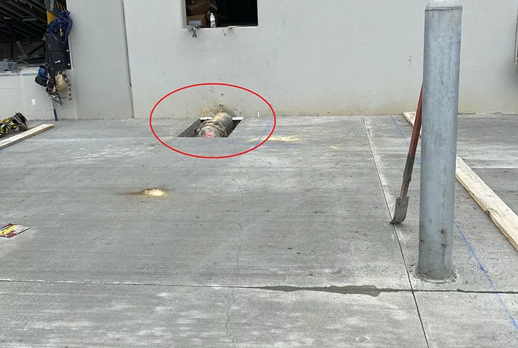
Each hydrant must be provided with a listed control valve installed within 20 feet of the fire hydrant (2019 NFPA 24 §7.1.1.2.2). In our experience, this is an often-missed requirement (see Figure 4). On numerous occasions, we have observed distances between the hydrant control valve and the hydrant of more than 20 feet. A quick conversation with the civil engineer can alleviate this issue if coordinated early in the design phase.

Every fire water connection to a water source must be equipped with a control valve, which is permitted to be listed or nonlisted, and indicating or nonindicating (2019 NFPA 24 §6.1). The type of isolation control valve is left to the jurisdiction’s discretion and should be confirmed during early due diligence discussions with the local AHJ.
Some jurisdictions will allow nonindicating gate valves to be installed in roadway boxes, while others will require that post-indicator valves (PIVs) be provided instead. PIVs offer the ability to visually confirm that the valve is open via a window installed on the top of a post, and the valves can more easily be located due to the aboveground post marking the location of each valve. For this reason, many jurisdictions in colder climates prefer PIVs in lieu of gate valves in roadway boxes.
It is imperative to identify if PIVs are required prior to laying out the underground pipe since PIVs cannot be installed in the roadway. They must be situated in parking lot islands or other spaces where they can be protected from mechanical damage and will not impede vehicle traffic.
Sectional control valves also are needed to limit the maximum number of fire protection connections (e.g., sprinkler system, fire hydrant, FDC) to six between valves (2019 NFPA 24 §6.6.1). This is another requirement that can be problematic when overlooked.
For example, relocation of a sprinkler riser lead-in without consideration of the sectional valve location(s) can result in the maximum number of connections being exceeded, which would then require the addition of an extra sectional valve to be code-compliant. In an instance where the jurisdiction required all isolation control valves to be the post-indicator type, this situation could prove to be an even more challenging problem to resolve.
Finally, some AHJs prefer that all control valves (e.g., backflow valves, sectional valves, etc.) be monitored by the fire alarm system. It is very important to understand if this requirement is being enforced, as it requires fire alarm conduit to be run underground to valve locations that may be substantially remote from the building and could add substantial cost to the project if overlooked.
By coordinating the design of exterior fire protection elements with other building systems and stakeholders, many of the issues listed here can be identified and resolved early in the process, leading to a smoother installation and a safer building.
Tracey Foster, SET, CFPS, is a senior fire protection technician with the Harrington Group and has been working in the fire protection industry since 2002. She is a member of the National Fire Protection Association and the Society of Fire Protection Engineers. Foster is an NFPA Certified Fire Protection Specialist, and she also holds a NICET Level IV certification in water-based systems layout.


