The Balance Between Ceiling Design and Fire Sprinkler Layout
Understanding the strategies may result in a more efficient sprinkler design and layout.
As fire protection engineers and system designers, Arup regularly collaborates with architects to coordinate sprinkler layout and design with the architectural vision. A long list of project-specific factors can complicate the sprinkler system design; however, one thing is always consistent — the way ceilings are designed has a significant impact on the sprinkler system.
As such, accurately and efficiently designing a fire protection system hinges on knowledge of ceiling design and its effect on sprinkler layout. This article introduces different strategies and select NFPA 13 requirements for laying out sprinklers under different types of ceilings.
Smooth Flat Ceilings
Smooth flat ceilings are arguably the easiest configuration to work with from a fire protection standpoint. In most situations, designers can complete the layout based on NFPA 13-compliant sprinkler spacing for the space’s occupancy hazard.
However, there are a few things to keep in mind. One of the most common types of smooth horizontal ceilings is acoustic ceiling tiles. It is preferable to keep sprinklers centered in acoustic tiles for aesthetic reasons.
There needs to be thorough coordination with lights, HVAC diffusers, occupancy sensors, fire alarm devices, exit signs and any other equipment that also may be vying for space in the ceiling. Placement of the sprinklers in relation to this other equipment shall ensure no obstruction to the sprinkler discharge as defined by NFPA 13.
Obstructed and Unobstructed Construction
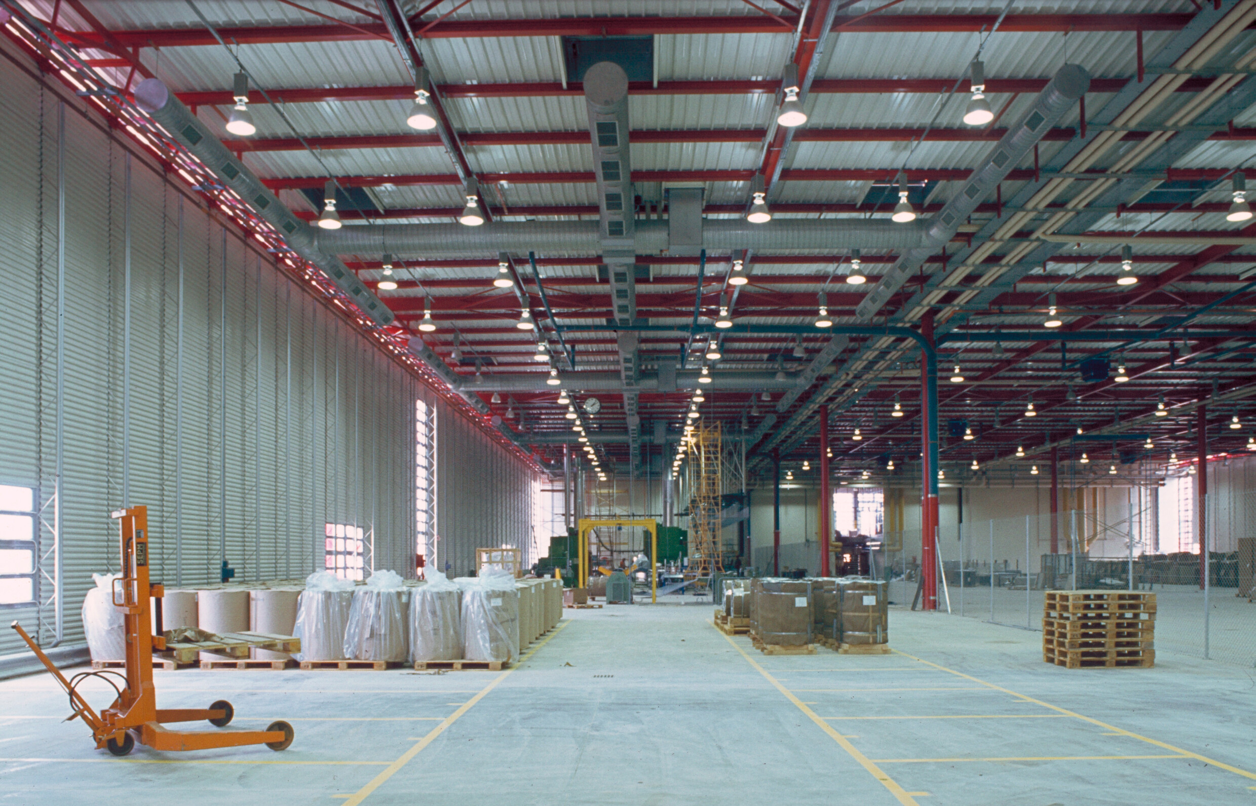
Often in back-of-house spaces, warehouses or spaces where a more “industrial feel” is sought after, there will be no ceiling in a space. Instead, architects opt only to have the floor deck above exposed, supported on steel beams, as shown in Figure 1.
Figures can be viewed from the January digital edition here.
Spaces open to a steel structure and floor deck above are as common as spaces with smooth, horizontal ceilings but offer a further challenge. This can be attributed to the fact that a space with a steel structure above can be classified either as unobstructed ceiling construction or obstructed ceiling construction by NFPA 13. Steel structures can either be unobstructed or obstructed construction, depending on the structure's geometry.
As implied by its name, unobstructed construction is a type of ceiling construction that does not “impede heat flow or water distribution in a manner that materially affects the ability of sprinklers to control or suppress a fire.” Conversely, obstructed construction is a type of ceiling where “beams, trusses, or other members impede heat flow or water distribution in a manner that materially affects the ability of sprinklers to control or suppress a fire.”
In a simplistic form, unobstructed and obstructed steel construction can be differentiated by one critical dimension: 7 feet 6 inches. Where a floor deck or continuous smooth bay is supported on girders or trusses spaced more than 7 feet 6 inches apart, then the ceiling is considered unobstructed construction. Where trusses and girders are spaced between 3 feet and 7 feet 6 inches apart, the ceiling is considered obstructed construction.
Sprinkler strategies for unobstructed and obstructed construction vary, so it is important to know the differences between them. Though maximum coverage areas under unobstructed and obstructed construction do not vary, the distance of the sprinkler deflector below the ceiling does.
Section 10.2.6 of NFPA 13 (2019) details the guidelines for deflector position below ceilings for standard pendant and upright sprinklers. Similar to smooth horizontal ceilings, the deflector for a sprinkler under unobstructed steel structure construction must be within 1 inch and 12 inches of the ceiling (shown in Figure 2).
However, this code requirement does not stand alone. Section 10.2.7.2.1.1 explains that obstructions less than or equal to 18 inches below the sprinkler deflector shall be considered to ensure the sprinkler’s spray pattern can adequately cover the floor below. The scope of avoiding obstruction to sprinkler spray is outside the scope of this article. That being said, it is heavily advised to familiarize oneself with those requirements to make sure there is no deficiency in sprinkler coverage.
When designing under obstructed steel construction, there may be multiple sprinkler design strategies to consider. Sprinkler design can closely resemble the strategy used in unobstructed construction spaces: install at least one sprinkler in each bay of obstructed sprinkler construction with its deflector 1 inch to 12 inches below the ceiling (shown in Figure 3).
However, alternate strategies can be used. Sprinklers can be installed with their deflectors 1 inch to 6 inches below the structural members as long as the deflectors are a maximum distance of 22 inches below the ceiling/roof deck (shown in Figure 4). Using this strategy will cut down on the number of sprinklers needed, therefore reducing the hydraulic demand of the system and cost of construction.
When designing under steel structure ceilings, it is important to know these requirements to coordinate with other disciplines. Not only can the spacing of structural members change throughout the course of project design, but designing under steel structure ceilings offers additional challenges when coordinating with other mechanical, electrical and plumbing (MEP) equipment.
Open-Grid Ceilings
Open-grid ceilings offer a special challenge from a fire protection standpoint. The term open-grid ceiling refers to a design where a ceiling is installed at a certain elevation, but it does not make a fully concealed space above the ceiling (see Figure 5).
This can be a challenge from a fire protection perspective because of the way the open grid potentially delays sprinkler activation. Sprinklers activate primarily due to the heat transfer from the smoke plume and hot upper gas layer/ceiling jet to the sprinkler’s thermal element. Once the thermal element/fusible link operates, water is released from the sprinkler.
When an open-grid ceiling is introduced, the perforations in the ceilings may not allow heat to fully collect around a sprinkler at the same elevation. Since hot gases can seep into the space above the ceiling, the sprinkler at the open-grid ceiling level might not activate. As such, in spaces with an open-grid ceiling, sprinklers will need to be installed at the higher ceiling level.
However, a second issue can arise with the use of open-grid ceilings. The activation of a sprinkler at the high ceiling level will discharge water, but the presence of the open-grid ceiling below can obstruct the spray pattern of that sprinkler. If the open-grid ceiling is not open enough to the space above, or if there is not enough space between the sprinkler deflector and the open-grid ceiling, further requirements need to be met to have an NFPA 13-compliant sprinkler system.
As such, Section 9.3.10 of NFPA 13 (2019) outlines the requirements for installing open-grid ceilings below sprinklers:
“9.3.10 Open Grid Ceilings. Open-grid ceilings shall only be installed beneath sprinklers where one of the following is met:
“1. Open-grid ceilings in which the openings are 1/4 inch or larger in the least dimension, where the thickness of depth of the material does not exceed the least dimension of the opening, and where such openings constitute 70 percent of the area of the ceiling material.”
The ceiling in Figure 6 is an example of a compliant open-grid ceiling. It satisfies all three of the stipulations in the NFPA 13 code section referenced previously — the openings are more than 1/4-inch wide, the ceiling is more than 70 percent open, and the distance between openings (Dimension A) is greater than the depth of the ceiling (Dimension B).
The ceiling in Figure 7 is noncompliant because the openings in the open-grid ceiling are less than 1/4 inch.
The ceiling in Figure 8 is noncompliant because the depth of the material (Dimension B) is greater than the dimensions of the openings in the ceiling (Dimension A).
The ceiling in Figure 9 is noncompliant because the area inside the blue dotted lines is less than 70 percent of the total ceiling area.
If a ceiling is designed to be compliant with the NFPA 13 section previously noted, then it can be installed below sprinklers without an additional layer of sprinklers below the open-grid ceiling. There are then additional requirements for the distance between the sprinkler’s deflector and the upper surface of the open-grid ceiling. These requirements, which depend on sprinkler spacing and occupancy hazard, are outlined in Table 1.
Note that just because an open-grid ceiling is not compliant with the previous section from NFPA 13 does not mean it cannot be installed in a building. The installation of a noncompliant ceiling means that sprinklers are required above and below the ceiling. If sprinklers are installed above and below the ceiling, a baffle needs to be installed around the lower sprinkler to avoid cold soldering.
Cold soldering occurs when discharged water from the sprinkler above cools the thermal element of the sprinkler below, preventing or delaying its activation in the event of the fire. The required baffle will prevent that water from contacting the thermal element of the sprinkler, thus circumventing the possible issue.
To lower the cost of construction and make coordination across disciplines easier, it can be advantageous to discuss the use and scope of open-grid ceilings with architects and building owners. If an open-grid ceiling can be changed slightly during the design phase to comply with NFPA 13, that cuts the number of sprinklers needed more or less in half.
It often has meant attempting to make the ceiling more open to achieve the 70 percent open mark, or keeping the open-grid ceiling low enough to give enough space between a sprinkler deflector and the top of the ceiling assembly. Whether you are trying to omit sprinklers for financial reasons, aesthetic reasons or ease of coordination and construction, knowledge of open-grid ceilings can help toward an optimal code-compliant fire protection design.
It is important to understand the details of the NFPA 13 requirements related to sprinkler installations/layouts in various ceiling configurations. These strategies allow fire protection engineers and system designers to help influence the ceiling design that may, in turn, result in a more efficient sprinkler design and layout. They also allow designers to recognize the constraints of their own design to maximize coordination with other disciplines in buildings where MEP distribution space is at a premium.
Though this article is not an exhaustive list of strategies nor NFPA 13 requirements, the information about a ceiling’s effect on sprinkler design above aims to aid in future designing of fire sprinkler systems.
Figures can be viewed from the January digital edition here.
Jack DeVine, EIT, is a fire and life safety consultant in Arup’s Boston office. He has a master’s degree in fire protection engineering from Worcester Polytechnic Institute and has been at Arup for the course of his professional life. He has growing experience in fire sprinkler and fire alarm design as well as code consulting, egress modeling and performance-based fire modeling.
Robert Accosta Jr., PE, is a licensed fire protection engineer in Arup’s New York office and serves as an alternate member on the NFPA 13 Technical Committee on Sprinkler System Installation Criteria. His expertise focuses on fire protection systems design and life safety code consulting from project inception through beneficial occupancy and closeout. Acosta is the past president for the Society of Fire Protection Engineers, New York Metropolitan Chapter.