Demystifying Flame Rectification
The pilot flame’s only role is to be an electrical conductor that acts like a switch with a short time delay.

Over the last couple of years, I’ve sold most of the remaining HVAC parts and components I had. Sometimes, I wish I hadn’t, but there’s only so much you can store in a 410-square-foot shop. Right? And moving heavy things cross-country from Chicago to Las Vegas isn’t the cheapest thing one can do.
I did what I had to do but I’m not going to lie, it stung a bit. I grew used to having everything under the sun in stock at my disposal. And with the out-of-control price increases we’ve all faced this year, the sting keeps stinging me from time to time.
I did keep some parts, but I’ll likely never use them because of the equipment I’ve been installing in our home. Almost everything is going to require OEM parts. I knew if I didn’t get creative, I’d have to sell these stored parts for pennies on the dollar. It’s either that or I let them sit on a shelf until they’ve become obsolete.
Neither appealed to me, so I decided to start putting them to good use. I could pay it forward and maybe teach a technician here or there a thing or two. I have a limited number of words to work with, so let’s get to it.
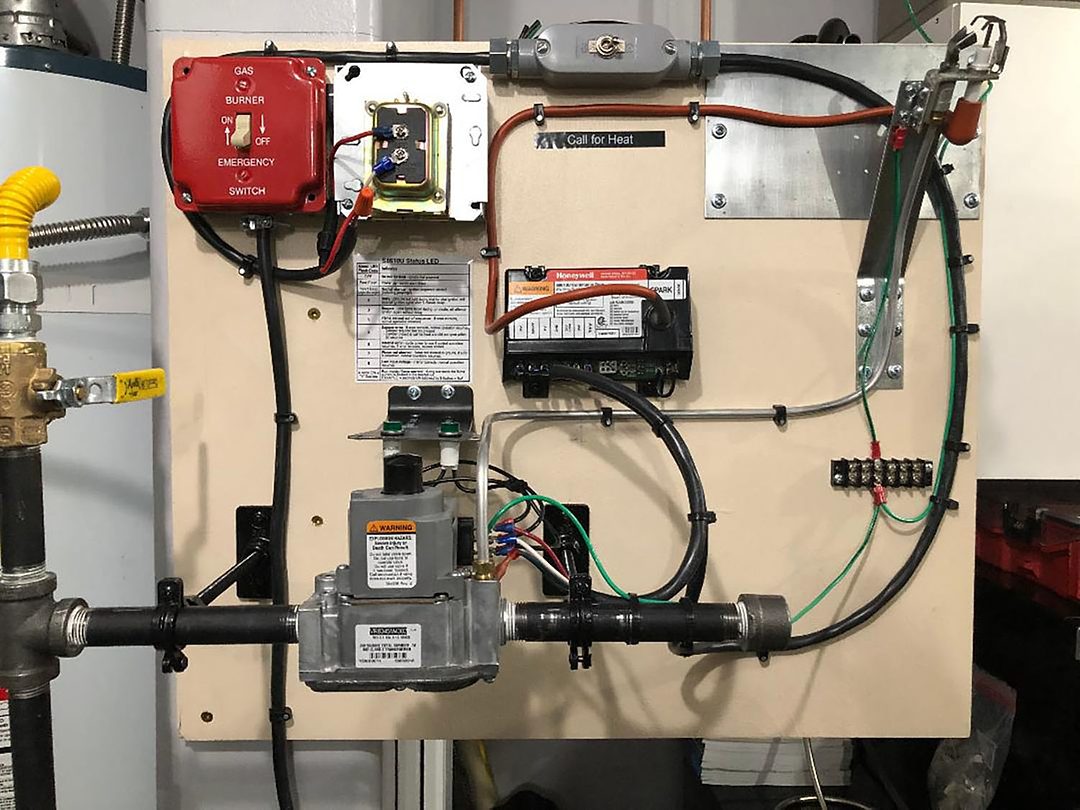
From my dwindling stock, I took an S8610U3009 ignition control, a VR8345M4302 gas valve, and a Q345M1305 pilot burner and mounted them on a small piece of 3/4-inch plywood. I then added electric: a 40VA transformer; service switch; a toggle switch, which provides the call for heat; and a 3-amp fuse on the secondary of the transformer.
Next, I hooked up some 1/2-inch gas pipe to it and ran 1/4-inch aluminum tubing from the gas valve to the pilot burner. I’d be lying if I said it wasn’t fun putting together this spark ignition trainer because I had a blast. It’s not every day I get to do this kind of hands-on stuff anymore. But I didn’t do it just for kicks. I did it to shed some light on what I know about flame rectification in a way that’s concise and, I hope, easy to understand. That’s the whole point of this.
Before I go any further, I’m going to throw in a few definitions first. No need to read them now, but they’re here for your reference should you need them.
• Microamp. It is 1/1,000,000 of an amp or 0.000001 amps. Yes, literally one in a million.
• Microamp symbol. µA
• Flame rectification. The process of converting alternating current (AC) to direct current (DC), where the flame acts as the rectifier.
• Rectify. To convert alternating current to direct current.
• Ion. An atom or group of atoms with an unequal number of electrons (–) and protons (+).
• Ionization. The process by which electrically neutral atoms or molecules are converted to electrically charged atoms or molecules (ions).
• Electrode. An electrical conductor used to make contact with a nonmetallic part of a circuit. (I threw in this definition because, in this case, the pilot burner hood also acts as an electrode when proving flame.)
Spark ignition process
Let’s take a quick run through the sequence of operations when everything is working properly.
1. A call for heat is simulated through the toggle switch, top center of the board.
2. 24 V are sent from the transformer through the thermostat to the ignition module’s TH-W terminal. The circuit is completed through the S8610U’s 24V (GRD) terminal back to the transformer’s C terminal and then to a good grounding source. In the real world, this circuit would need all the required safety controls and switches.
3. After the ignition module does a self-check and a pre-purge is performed (if used), the trial for pilot flame begins. The pilot valve of the VR8345M is energized from the PV and MV/PV terminals of the ignition control. At the same time, AC voltage from the module is applied to the ignitor/sensor, with the spark bridging the gap between the tip of the ignitor to the ground strap directly above it. Now, the pilot flame is established.
Here’s where the magic happens. Flame rectification, in all its glory, proves there’s a pilot burning just waiting to ignite the main burner. Here’s how that happens.
4. In this example, we’re working with a one-rod or local sense system. This means that the igniting and sensing all come from a single rod (electrode).
5. It also uses only one cable, the 30-inch orange cable pictured above.
6. Heat from the pilot flame causes atoms or groups of atoms (molecules) to bash into each other like a screen door banging in a windstorm. This violent crashing causes some electrons to be freed from the molecules. As a result, the flame becomes ionized due to the free electrons and positive ions.
This allows the flame to act as a conductor and a small current can now flow through it. This activity is called flame ionization.
7. Not all flames are ionized, or some are more ionized than others. It’s all dependent on the temperature of the flame. A candle flame is unlikely to be hot enough to conduct/rectify electricity to prove flame. Think of a dirty, floating pilot flame.
8. To establish flame presence without the potential of a short to ground simulating flame, the current must be changed from AC to DC. Flame rectification is achieved by inserting a grounding electrode (burner/hood) in the flame that’s at least four times the size of the ignitor/sensor. The larger grounding area allows it to hold electrons, resulting in a higher current in the flame through the first half cycle, and the opposite takes place during the second half cycle.
The current flattens out so as not to be AC and not quite flat enough to be a true DC current, but close enough for this purpose. The ignition module will only accept a current that is not alternating current. Any AC signal will be rejected.
7. It’s important to know that the pilot flame needs to be clean, blue and properly adjusted, but heating the sensor plays no role in proving pilot. The flame itself is the conductor: Because the ground electrode (pilot hood) and the sensor electrode (ignitor/sensor) are different sizes, the current becomes directional and is measured in DC microamps.
8. Once the pilot flame is proved, the ignition control module gives it a thumbs up, sends voltage via the MV and MV/PV terminals to the main gas valve, which now opens and fires up the burner, and the sparking stops. We now have a fully operational intermittent ignition system.
Maintenance and service
• Grounding. This is so important and so often overlooked. Here’s how I do it.
I make sure I have a common ground between the ignition control module and pilot burner, often using the gas valve ground terminals as a connecting point with good, clean, tight connections all the way to the grounding source. If the boiler or furnace jacket isn’t giving you a good ground, run a separate green wire to a clean steel gas pipe or cold-water pipe (see Figure 2).

Without this, it could end up being one of those instances where it works every time you’re on-site, but you get a callback because of a nuisance lockout two hours or two days later. It only takes a few seconds to check while you’re there the first time.
• Polarity. Reversed polarity is another one of the potential nuisance lockouts or service callbacks. It’s simple enough to check. From the R terminal on the transformer secondary to ground, the voltage should read 24 V. From the C terminal to ground, 0 V. If it’s reversed, the wires connected to the primary are reversed.
Don’t take for granted that because a power source black wire is connected to the black primary wire, it’s correct. Check with a voltmeter to confirm that the black wire going to the primary is 120 V to ground. I’ve seen the wires crossed two boxes away or at the main panel. Do your best not to assume anything.
• Ignition cable. The maximum length is 36 inches. Check for continuity of the cable using an ohmmeter. You should get around 0.1 to 0.2 ohms. Also, examine the cable for cracking, discoloring or wear. Replace as necessary.
• Spark intensity. You should get a strong arc for the standard 1/8-inch gap. There is a method to check spark intensity up to a 1/2-inch, but I’m going to refer you to the manufacturer’s instructions for that. The module generates more than 10,000 V, so I think it’s better you read it directly from the source.
• Ignitor. The kanthal rod should be kept clean. There are so many schools of thought on what to use when cleaning these things, and just as many saying you should do the exact opposite. Here are some that are often mentioned — emery cloth, steel wool, a dollar bill, fine ScotchBrite, etc.
Me? I would typically use fine steel wool or a fine ScotchBrite pad used gently. The dollar bill trick works well, but I rarely carried cash, so it usually wasn’t an option for me.
Check along the length of the rod with an ohmmeter. Resistance should remain consistent. If big changes or loss of continuity are noticed, replace.
Also, with an ohmmeter and everything connected, check from the tip of the electrode to ground. There shouldn’t be any continuity. If so, check each component one by one to find the short to ground.
You should have dry, clean, tight connections. Also, make sure no cracks or chips are in the ceramic enclosing the electrode. (See Figure 3.)

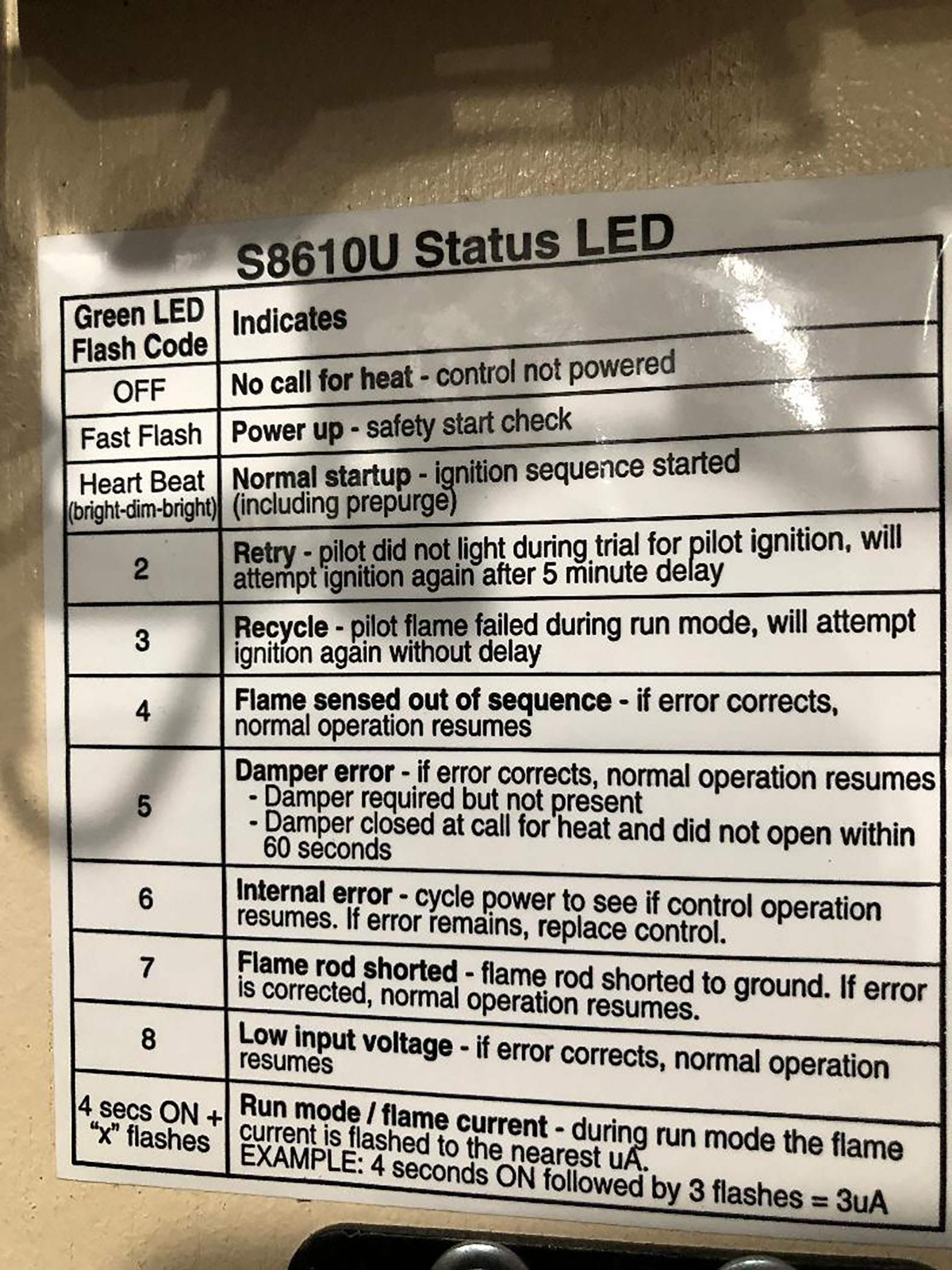
Most of these ignition controls will include a fault code LED sequence, which is a big help in troubleshooting (see Figure 4). Just as important, if not more so, is understanding how these components work together.

Once you begin to understand that the pilot flame does not perform the same duty as it would with a system using a bimetallic element, thermocouple or a mercury-type sensor, the better off you will be. It’s not there to heat up anything. Its only role is to be an electrical conductor that acts like a switch with a short time delay.


