Mixing Valves in Hydronics: Multiple Temps or Multiple Headaches?
When applied properly, they can be a great option to effectively control the temperature to your heating circuits and maintain optimal comfort.

More than ever, it’s commonplace to have a wide variety of heat emitters in today’s hydronic heating systems. When sized, designed and installed correctly, comfort can come in the form of a fan coil, panel radiator or the application that has become synonymous with comfort — radiant floor heating.
These differing heat emitters will likely require a range of temperatures to satisfy the demands of the application. It’s also likely that during the design process, you will have identical heat emitters requiring different temperatures based on their size or the heat loss of the space. With your heat source only being capable of producing one temperature at a time and your heating demands coming at you all at once, independent temperature control becomes a necessity.
Taking just the right amount of high-temperature supply fluid and blending it precisely into the circuit to create the proper temperature can be done in a variety of ways. Four-way mixing valves and injection mixing systems can get the job done. If you’re feeling frisky, I would suggest looking up mini-tube distribution systems.
These are a few of your more elaborate options but let’s focus on three-way thermostatic mixing valves. While they are simple in design, thermostatic mixing valves are commonly misapplied and can cause more problems than solutions.
Location, location, location
One possible problem has to do with the location of your circulator in relation to your mixing valve. When circulating through one to provide heating to a space, it’s critical to realize that you’re dealing with a device with a thermostatic control element, two inlets, one outlet and a fierce determination to provide the correct proportions of hot and cold fluid to create that just-right temperature.
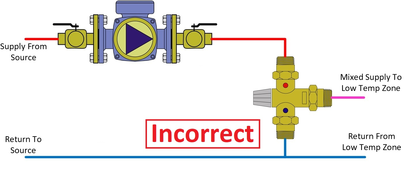
With such a one-track mind, the valve doesn’t care where your circulator is located. So, if you’re pumping into the hot side of your mix valve with your circulator (see Figure 1), your hot inlet is still an inlet and your mixed outlet is still an outlet, but now you’ve inadvertently turned your cold inlet into an outlet.

At this point, you’re no longer going to be able to pull in cooler fluid to create the perfect mixed temperature. You’ve also made a short circuit directly from supply to return, giving your BTUs no reason to go where they’re needed.
In one particular case of poor judgment I was read in on, the fix was to install a check valve on the now-turncoat cold inlet. This took care of that pesky short circuit problem and got some BTUs out to the space, but instead of controlling temperature, the mixing valve turned into a flow-limiting device. It closed down the hot inlet as the fluid temperature met and exceeded its set point.
The circulator must be located so it’s pumping away from the mixed outlet of the mixing valve (see Figure 2). This will ensure that the proper flow is maintained and the mixing valve sustains the correct temperature by determining which side the circulator pulls from.

Sizing matters
Trailing just behind the choice of circulator location, our next potential offense is undersizing the mixing valves. This transgression is usually the exact opposite in DHW mixing valve applications, where oversizing is fairly frequent. But I get it, it just makes sense that you should need a 1-inch mixing valve when you have a 1-inch pipe, sized correctly for moving 8 gallons/minute. You even went out of your way to verify that your circulator can move 8 gpm.
The problem is that most 1-inch mixing valves you’ll see at your local wholesale counter are low-lead and will be capable of either hydronic or DHW applications. These two-faced mixing valves will often have a pressure drop of 10 pounds/square inch (or more!) at 8 gpm. While it may be alright for DHW applications, it’s a guaranteed flow killer for the circulator you just picked out.
That 10-psi drop is a whopping 23 feet of head loss; when your circulator is only capable of 17 feet of head at a maximum, you’ll have little chance of it getting the job done. So, now you’ve come to a fork in the road; you’ll need to decide whether you want a more powerful circulator or a mixing valve with less pressure drop.
I do hope you weigh your options carefully. Consider that you’re certainly going to pay more for either approach upfront but with a larger circulator, you’ll be paying more for the electrical consumption over the life of the system.
It’s also wise to keep in mind how unnecessarily complicated these systems can get with many different supply temperature requirements. Let’s imagine that you just got the design work back on an upcoming job; you notice it’s calling for 108 F, 111 F, 116 F, 120 F, 127 F and 132 F supply fluid temperatures. It doesn’t mean you will have the heat source provide 132 F and then rely on five different mixing valves. This can easily be simplified.
Maybe adding a little bit of emitter to the zone requiring 132 F could drop it a few degrees. You’ll have three zones within 8 to 10 degrees of one another, which could easily be lumped into a single supply temperature zone being run at the highest required temperature. The last three zones are already fairly close; the same could be done here. So now, instead of six different temperature zones, you have two.
The higher of the two can be supplied directly from the heat source and the lower two with a mixing valve. You’ll provide a little more than what is required into two of the areas in each supply temperature zone, but this will be at very little detriment to the system. It will also greatly reduce the system's complexity and likely the cost of the job as well (see Figure 3).

When applied properly, mixing valves can be a great option to effectively control temperature to your heating circuits and maintain optimal comfort. I hope these tips help you to avoid future headaches and be a hero for your customers.


