By 1970, Louis J. Lefkowitz was a household name in New York and across parts of the United States. Height challenged with large feet, he had run an activist New York Attorney General office for many years by the time that I graduated from Lehigh University with a newly minted civil engineering degree. I wrangled a job as an environmental scientist in Louie’s new Environmental Protection Bureau in Manhattan. My job was to find pollution and help litigate an end to it.
One of the first things I did at the AG’s office was organize a public hearing on the future of solar as part of a smarter energy future for our state and country. Funny how things work. After three decades in that job, I did become a solar thermal designer and installer And coupled with plumbing design now, that’s been my focus ever since.
When I interviewed for the job five years ago as the solar thermal installer for a new NetZero all electric multifamily complex, the developer asked me if my thermal storage designs included PCMs – phase change materials. I told him that I surely could and maybe we could afford to install mutton tallow! Well, PCMs have not found a home there yet but we did install 26 drainback systems that today continue to preheat DHW very efficiently, thank you. We are reprising this success in a new and larger NetZero complex down the road now called Solara.
Electrification of buildings has become a policy imperative of numerous states concerned about climate change. They are implementing policies that aim to de-carbonize electricity production by greater reliance on renewable energy sources. If fossil fuels are used on site instead of electricity, opportunities to limit the adverse climate effects of our population’s lifestyle are wasted. That’s why states are incentivizing electric alternatives for heating and cooling.
Why solar thermal and PV?
The World Green Building Council defines a NetZero carbon building as a building that is highly energy efficient and fully powered from on-site and/or off-site renewable energy sources. Without solar collections, achievement of a NetZero carbon building is essentially impossible. While electric solar (PV) can achieve the goal all by itself, properly sized solar thermal systems yield superior energy performance per dollar. Hybrid hot water heat pump systems improve that result.
The way we’ve achieved NetZero at Solara (near Schenectady, New York) is by creating a very tight highly insulated building shell to minimize heat loss in the winter and limit heat gain in the summer. High efficiency appliances and hot water fixtures cut plug and hot water loads. Solar thermal and PV arrays capture more than enough energy to counterbalance electricity taken from the grid during the night and cloudy days.
Because of the high efficiency of the shell and appliances cuts electric loads so much, heating the hot water people use becomes a much larger proportion of energy consumption than in conventional buildings – a fact that adds to the justification for solar thermal systems in NetZero multifamily buildings. Yes, PV panels could generate the power to heat hot water. But their cost per watt of heat is higher and their watts per square foot output is much smaller as well.
Solara’s hybrid hot water production system
There are five major elements of a multifamily hot water production system working backwards: Fixtures, distribution piping, hot water storage, water heating devices and cold water supply. We will focus on the water heating portion in this article – preheating (solar thermal and heat pumps), primary heating (electric resistance elements) and side arm heating devices.
Here’s the spoiler. The schematic below of what we devised to cost-effectively minimize electricity consumption to create hot water for Solara’s 10 buildings.

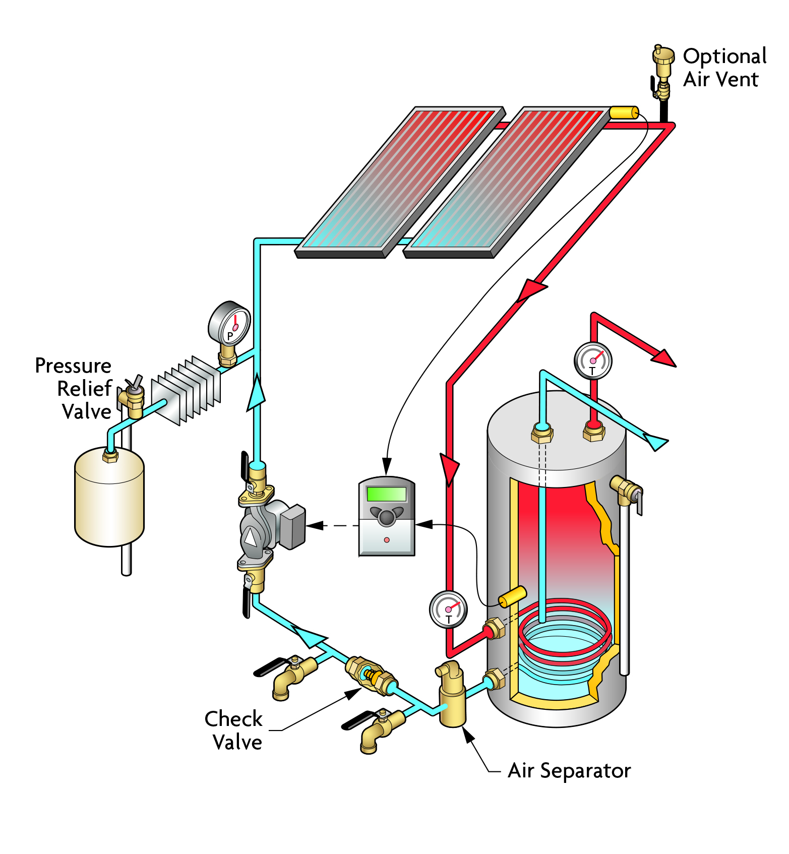
Let’s start with the solar thermal part of this design. In simple terms, solar thermal systems consist of arrays of properly angled flat panels or evacuated tubes that capture energy from incoming sunlight, heating a transfer fluid (HTF) that delivers that energy to a heat storage tank via a pumped line set.
In areas where outdoor temperatures fall below say, 40 degrees at night, solar designers choose antifreeze as the HTF or a drainback design where the HTF returns to an indoor tank where it won’t freeze. A controller compares the sensor temperatures in the storage tank and in the collectors, energizing the pump only when the “delta T” between them is greater than about 4-6 degrees.
The other loop design many installers choose is the pressurized lineset approach. This design requires an expansion tank, pressure relief capability and antifreeze to preclude freeze up in much of the U.S. Pressurized systems can reduce the parasitic energy loads for HTF circulation but raise more leakage and other pressure related problems - like steamback issues. Drainback systems raise problems with pump cavitation and demand more power to initially raise the HTF to the roof (after the loop siphon is established, power consumption drops, however).

At Solara, we chose an open loop drainback system because of its simplicity – water stored in a large highly insulated atmospheric but covered tank that is pumped to the roof arrays when the sun provides advantageous thermal conditions. This water serves as both the heat storage medium and the loop HTF. Cold water feeds coils of corrugated stainless steel tubing submerged in this water and thereby warms it before entering DHW back up tanks.

While pressure tanks are a standard fixture in utility rooms, much larger round or square non-pressurized “heat vaults” are finding favor because they can be better insulated and store much more heat much longer.
We chose 1,200 gallon square tanks because they offer R-30+ insulation (standard pressure tanks generally offer only R-14) and fit efficiently into rooms that are rectilinear. Both tank shapes are either folded or pre-fabbed from a kit that are easy to install. Just add water, heat exchangers and don’t stir (if you want stratification)! The installed price per unit of heat (btu) stored is very favorable, even including the heat exchangers (less than half the price per gallon stored) and they require minimal maintenance for long periods.

Tank size for the solar heat vault and backup tanks require careful design. For solar tanks, bigger is generally better because sunshine, at least in the Northeast, is not a reliable commodity and water is cheap. Many solar books suggest 1 gallon of stored water per square foot of collector. We’ve found that NE solar systems perform better with ratios double that, a feature we call the thermal flywheel. With ratios of 2 gallons per square foot, we rarely witness our solar panels reaching maximum tank temperature settings of 170 degrees, even in the summer. Granted, the preheat temperatures in the cooler cloudier months are rather low. But, that’s where the heat pumps kick in to carry the extra load.
In order to transfer solar derived heat stored in the water in the vault, heat exchangers are required. We chose on-site fabricated corrugated stainless steel coils suspended in the tanks on stainless rod frames. Other installers choose double pumped brazed flat plate or shell and tube heat exchangers.
Traditional Solar Hot Water Backup systems
After the solar preheated water (SHW) emerges from the coil manifold on the side of the heat vault, it enters one or two traditional hot water tanks, each with one or two electric elements and a helical coil heat exchanger (HX) submerged at the bottom. These tanks serve two purposes. First, the hot water inside provides a reserve of hot water for large DHW draws that exceed the instantaneous heat capacity of the elements and HX supply. Secondly, the tank(s) provide a place for the electric elements to raise the water to sufficient temperatures for subsequent fixture use (if the heat pumps or solar contributions fall short). Everyone has seen and probably changed an electric resistance element. Most tanks have one or two of them, one of which fires at a time usually, the upper one first.
Unless your client is willing to pay the ASME premium for large pressure tanks, most utility rooms sport multiple 119 gallon tanks plumbed in parallel or in series. These tank “farms” are expensive to purchase and install. More hot water storage also requires more sanitation effort as well.
As an experiment to reduce back-up storage volumes, we installed a hybrid arrangement on just one tank – an electric on-demand sidearm heater that increases the instantaneous heating capacity of the installation. When a set point controller senses that temperature near the bottom of a tank has fallen too far, it energizes a small circulator that moves the “cooler” water from the bottom of the tank through the electric heater which heats the moving water about 30 degrees and deposits it in the upper zones of the tank. This “boost” heater can allow us to serve our clients with one instead of two tanks.
Heat Pumps hybridize hot water systems
Yes – in the northeast U.S., we need electric back up capacity for our SHW systems. The old reliable way is electric resistance elements – those simple devices that act like light bulbs under water. Their efficiency is high. Most of the electricity is translated into btus in the water. But now we can do better, thanks to the emergence of heat pumps (HPs) with efficiencies exceeding 400 percent; a coefficient of performance (COP) of 4.0.
As most readers know, there are air-to-water (A-W) and water-to-water (W-W) heat pumps on the market today. Some A-W HPs are electric hot water heater hybrids and are used indoors. A small HP handles most of the hot water heat load but electric resistance serves as a standby source. Although heat inside the building fuels this HP, some devices can be ducted to the outdoors as well. Indoor HPs would not work well in a NetZero building, however, because waste heat is rarely available.
Heat pumps rely on gas/liquid phase changes to achieve their high COPs. Sadly, most of these refrigerant gases pose global warming potential (GWP) and can deplete the ozone layer. A-W HPs rely on CO2, R410A and R134. CO2 has almost no climate and ozone impacts. The other two have hundreds of times more. Several companies offer CO2 based HPs, one of which is a candidate for this size building. We had to reject that device because it was incompatible with a solar preheat system and because it uses water as the HTF – a freeze up risk we did not want to take. Because R410a has the best cold weather and temperature range performance, we limited our choices to that refrigerant.
Larger A-W HPs are splits. Pumped HTF carries heat from an outdoor fan compressor box to an HX inside the building, and relies on R-410A and R-134 refrigerants. The Sanden brand specifies water as the HTF (well adapted for temperate climates), most others use antifreeze to preclude freeze up damage. W-W HPs rely on fluids for heat. Many are “geo” type heat pumps which rely on deep wells or slinky HDPE piping buried in the ground or suspended in a lake. In general, the W-W HPs cost more to install and may have greater pump power loads.
We chose cold climate A-W split R-410A HPs for Solara because their size (2-3 tons) fit our estimated supplemental load estimates in the winter, their cost was reasonable, and because their installation was easy. Yes, the performance of A-W HPs can suffer during cold weather but the number of hours of very cold weather these days has declined substantially of late. One of the three makes we bought has, however, done very well during testing at 10 degrees F. We will run these heat pumps about 40-50 percent of the year. The solar system carries most of the load during the rest of the year. This winter, we assessed the performance of these heat pumps and chose two metrics (btus/hr produced/amp and COPs) and raw heat (btu/hour) to gauge performance.

Solar sizing of the hybrid hot water system
Let’s consider a very important element of hybrid DHW production design – namely sizing the heat vault and panel arrays. Our design process consisted of reliance on solar/HP simulations (we used Polysun and TRNSYS software) for various load assumptions. By varying the areas of the solar arrays, volume of the heat vaults and capacity of the heat pumps in many sensitivity runs, we were able to find a sweet spot where installation costs were minimized while effectively meeting the estimated loads. The result was minimized electricity consumption!
For these NetZero all-electric buildings, finding this sweet spot required consideration of cost and performance tradeoffs between thermal and PV solar arrays. The smaller the solar thermal array, the greater the loads will be carried by the heat pumps and electric resistance elements – devices that are fired by PV panels (and the grid on cloudy days). Since the cost/kw (or btu) of PV panels is several times that of thermal panels, “right sized” thermal arrays can minimize PV panel investment. However, if thermal arrays are too big, their cost/btu produced annually increases because they produce more heat during the summer than can be stored or used. This tradeoff analysis is not trivial. It requires an iterative approach because each scenario not only needs an energy production simulation but also a cost estimate for each major element.

In the end, we chose to downsize the thermal arrays to a more cost effective size (23.3 square feet/apartment compared to 46.7 ft2 per apartment at the earlier NetZero village complex). No A-W HPs were installed there. But, we upsized the heat vault volume from 1.03 gallons per ft2 of panel to 2.14 gallons/ft2. For cloudy-day hot water production, we chose twin 108 gallon HX DHW tanks plumbed in parallel, 5,500 watt (4,700 watts at 208 vac) electric elements (one per tank) and one A-W HP per 24 apartment building. So far, the SHW systems have carried the bulk of the hot water load almost completely during May through September while the heat pump hybrid approach has made up the daily heat deficits for the rest of the year.
The next article
In the next article, we will discuss how we have evaluated fixture performance and modified the normal trunk-branch-twig DHW distribution system design to a small diameter trunk – no branch – home run 3/8” tubing twig approach. The goal is simple: minimize wasted heat and water and increase delivery times to around 15 seconds for the showers and kitchen sinks in the buildings.


